
User Manual
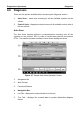
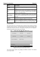
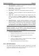
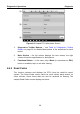
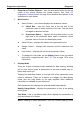
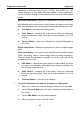
Table Of Contents
- Trademarks
- Copyright Information
- Disclaimer of Warranties and Limitation of Liabilities
- For Services and Support:
- Safety Information
- Contents
- Chapter 1 Using This Manual
- Chapter 2 General Introduction
- Chapter 3 Getting Started
- Chapter 4 Diagnostics Operations
- Chapter 5 Data Manager Operations
- Chapter 6 MaxiFix Operations
- 6.1 Navigation
- The Header
- Select Vehicle Button
- The “Select Vehicle” button on the Header allows you to specify the vehicle which you want to reference on MaxiFix, by selecting each of the vehicle attribute from a sequence of option lists. This feature helps to filter out the searches that allow on...
- 6.1.1 Terminology
- 6.2 Operations
- 6.1 Navigation
- Chapter 7 Settings Operations
- Chapter 8 Shop Manager Operations
- Chapter 9 Update Operations
- Chapter 10 VCI Manager Operations
- Chapter 11 Remote Desk Operations
- Chapter 12 Support Operations
- Chapter 13 Training Operations
- Chapter 14 Quick Link Operations
- Chapter 15 MaxiScope Operations
- 15.1 Safety Information
- 15.2 Glossary
- 15.3 MaxiScope Module
- 15.4 Screen Layout and Operations
- 15.4.1 Top Toolbar
- Math Channel
- A math channel is virtual channel generated by mathematical function of the input channel. It can be displayed in a scope or XY view in the same way as an input signal, and like an input signal it has its own measure axis, scaling and color. The MaxiS...
- Probe
- A probe is any transducer, measuring device or other accessory that you connect to an input channel of your MaxiScope module.
- Reference Waveform
- Recall Reference
- 15.4.2 Functional Buttons
- 15.4.3 Measurement Grid
- 15.4.4 Measurement Rulers
- 15.4.5 Functional Buttons
- 15.4.1 Top Toolbar
- 15.5 Troubleshooting
- 15.6 MaxiScope Firmware Update
- Chapter 16 Digital Inspection Operations
- Chapter 17 Maintenance and Service
- Chapter 18 Compliance Information
- Chapter 19 Warranty

Diagnostics Operations Diagnosis
37
Name
Description
Pause
Suspends scanning and changes to show the Continue
button.
OK
Confirms the test result, and continues to the system
diagnosis after selecting the required system by tapping
the item in the Main Section.
Quick Erase
Deletes codes. A warning message screen will display
to inform you of possible data loss when this function is
selected.
Report
Displays the diagnostic data in the report form.
Save
Saves the diagnostic session as a history record, this
allows you to quickly restore access to the test systems.
Control Units
This option allows you to manually locate a required control system for testing
through a series of choices. You simply follow the menu driven procedure, and
make proper selection each time; the program will guide you to the diagnostic
function menu after a few choices you’ve made.
Figure 4-8 Sample Function Menu Screen
The Function Menu options vary slightly for different vehicles. The function
menu may include: