
User Manual

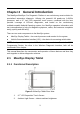
Table Of Contents
- Trademarks
- Copyright Information
- Disclaimer of Warranties and Limitation of Liabilities
- For Services and Support:
- Safety Information
- Contents
- Chapter 1 Using This Manual
- Chapter 2 General Introduction
- Chapter 3 Getting Started
- Chapter 4 Diagnostics Operations
- Chapter 5 Data Manager Operations
- Chapter 6 MaxiFix Operations
- 6.1 Navigation
- The Header
- Select Vehicle Button
- The “Select Vehicle” button on the Header allows you to specify the vehicle which you want to reference on MaxiFix, by selecting each of the vehicle attribute from a sequence of option lists. This feature helps to filter out the searches that allow on...
- 6.1.1 Terminology
- 6.2 Operations
- 6.1 Navigation
- Chapter 7 Settings Operations
- Chapter 8 Shop Manager Operations
- Chapter 9 Update Operations
- Chapter 10 VCI Manager Operations
- Chapter 11 Remote Desk Operations
- Chapter 12 Support Operations
- Chapter 13 Training Operations
- Chapter 14 Quick Link Operations
- Chapter 15 MaxiScope Operations
- 15.1 Safety Information
- 15.2 Glossary
- 15.3 MaxiScope Module
- 15.4 Screen Layout and Operations
- 15.4.1 Top Toolbar
- Math Channel
- A math channel is virtual channel generated by mathematical function of the input channel. It can be displayed in a scope or XY view in the same way as an input signal, and like an input signal it has its own measure axis, scaling and color. The MaxiS...
- Probe
- A probe is any transducer, measuring device or other accessory that you connect to an input channel of your MaxiScope module.
- Reference Waveform
- Recall Reference
- 15.4.2 Functional Buttons
- 15.4.3 Measurement Grid
- 15.4.4 Measurement Rulers
- 15.4.5 Functional Buttons
- 15.4.1 Top Toolbar
- 15.5 Troubleshooting
- 15.6 MaxiScope Firmware Update
- Chapter 16 Digital Inspection Operations
- Chapter 17 Maintenance and Service
- Chapter 18 Compliance Information
- Chapter 19 Warranty

iv
Contents
CHAPTER 1 USING THIS MANUAL ...................................................................... 1
1.1 CONVENTIONS ............................................................................................... 1
1.1.1 Bold Text ............................................................................................. 1
1.1.2 Terminology ........................................................................................ 1
1.1.3 Notes and Important Messages ........................................................... 1
1.1.4 Hyperlinks ........................................................................................... 1
1.1.5 Procedures .......................................................................................... 2
CHAPTER 2 GENERAL INTRODUCTION ............................................................... 3
2.1 MAXISYS DISPLAY TABLET ................................................................................. 3
2.1.1 Functional Description ......................................................................... 3
2.1.2 Power Sources ..................................................................................... 5
2.1.3 Technical Specifications ....................................................................... 6
2.2 VCI – WIRELESS DIAGNOSTIC INTERFACE .............................................................. 7
2.2.1 Functional Description ......................................................................... 7
2.2.2 Technical Specifications ....................................................................... 8
2.2.3 Power Sources ..................................................................................... 8
2.3 VCI – J2534 ECU PROGRAMMING DEVICE .......................................................... 8
2.3.1 Functional Description ......................................................................... 8
2.3.2 Power Sources ....................................................................................10
2.3.3 Technical Specifications ......................................................................10
2.4 ACCESSORIES KIT ...........................................................................................11
2.4.1 Main Cable .........................................................................................11
2.4.2 OBD I Adapters ...................................................................................11
2.4.3 Other Accessories ...............................................................................12
CHAPTER 3 GETTING STARTED ..........................................................................14
3.1 POWERING UP ..............................................................................................14
3.1.1 Application Buttons ............................................................................15
3.1.2 Locator and Navigation Buttons .........................................................16
3.1.3 System Status Icons ............................................................................17
3.2 POWERING DOWN .........................................................................................18
3.2.1 Reboot System....................................................................................18
3.3 INSTALLING COMPUTER SOFTWARE ....................................................................18
3.3.1 Printing Operation ..............................................................................19
CHAPTER 4 DIAGNOSTICS OPERATIONS ............................................................20