
User Manual
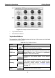
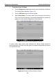
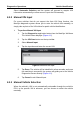
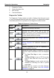
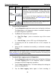
Table Of Contents
- Trademarks
- Copyright Information
- Disclaimer of Warranties and Limitation of Liabilities
- For Services and Support:
- Safety Information
- Contents
- Chapter 1 Using This Manual
- Chapter 2 General Introduction
- Chapter 3 Getting Started
- Chapter 4 Diagnostics Operations
- Chapter 5 Data Manager Operations
- Chapter 6 MaxiFix Operations
- 6.1 Navigation
- The Header
- Select Vehicle Button
- The “Select Vehicle” button on the Header allows you to specify the vehicle which you want to reference on MaxiFix, by selecting each of the vehicle attribute from a sequence of option lists. This feature helps to filter out the searches that allow on...
- 6.1.1 Terminology
- 6.2 Operations
- 6.1 Navigation
- Chapter 7 Settings Operations
- Chapter 8 Shop Manager Operations
- Chapter 9 Update Operations
- Chapter 10 VCI Manager Operations
- Chapter 11 Remote Desk Operations
- Chapter 12 Support Operations
- Chapter 13 Training Operations
- Chapter 14 Quick Link Operations
- Chapter 15 MaxiScope Operations
- 15.1 Safety Information
- 15.2 Glossary
- 15.3 MaxiScope Module
- 15.4 Screen Layout and Operations
- 15.4.1 Top Toolbar
- Math Channel
- A math channel is virtual channel generated by mathematical function of the input channel. It can be displayed in a scope or XY view in the same way as an input signal, and like an input signal it has its own measure axis, scaling and color. The MaxiS...
- Probe
- A probe is any transducer, measuring device or other accessory that you connect to an input channel of your MaxiScope module.
- Reference Waveform
- Recall Reference
- 15.4.2 Functional Buttons
- 15.4.3 Measurement Grid
- 15.4.4 Measurement Rulers
- 15.4.5 Functional Buttons
- 15.4.1 Top Toolbar
- 15.5 Troubleshooting
- 15.6 MaxiScope Firmware Update
- Chapter 16 Digital Inspection Operations
- Chapter 17 Maintenance and Service
- Chapter 18 Compliance Information
- Chapter 19 Warranty

Diagnostics Operations Navigation
32
Name
Button
Description
Data
Logging
Records the communication data and ECU
information of the test vehicle. The saved data can
be reported and sent to the technical center via the
internet.
You can go to the Support application to follow up
the processing progress, see Data Logging on page
98 for detailed information.
Send
Tapping this button submits the Data Logging report
to the technical center via the internet.
To print data in Diagnostics
1. Tap the Diagnostics application button from the MaxiSys Job Menu.
The Print button on the diagnostic toolbar is available throughout
the whole Diagnostics operations.
2. Tap Print and a drop-down menu appears.
a) Print This Page – prints a screenshot copy of the current
screen
b) Print All Page – prints a PDF copy of all displayed data
3. A temporary file will be created and sent to the computer for
printing.
4. When the file is transferred successfully, a confirmation message
displays.
NOTE: Make sure the display tablet is connected to the computer network,
either via WiFi or LAN, before printing. For more instructions on printing, see
Printing Operation on page 18 for details.
To submit Data Logging reports in Diagnostics
1. Tap the Diagnostics application button from the MaxiSys Job Menu.
The Data Logging button on the diagnostic toolbar is available
throughout the whole Diagnostics operations.
2. Tap the Data Logging button. The button displays blue during the
active recording process.
3. Tap the Data Logging button again to finish recording. A