
User Manual
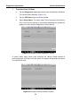
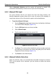
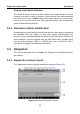
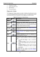
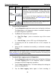
Table Of Contents
- Trademarks
- Copyright Information
- Disclaimer of Warranties and Limitation of Liabilities
- For Services and Support:
- Safety Information
- Contents
- Chapter 1 Using This Manual
- Chapter 2 General Introduction
- Chapter 3 Getting Started
- Chapter 4 Diagnostics Operations
- Chapter 5 Data Manager Operations
- Chapter 6 MaxiFix Operations
- 6.1 Navigation
- The Header
- Select Vehicle Button
- The “Select Vehicle” button on the Header allows you to specify the vehicle which you want to reference on MaxiFix, by selecting each of the vehicle attribute from a sequence of option lists. This feature helps to filter out the searches that allow on...
- 6.1.1 Terminology
- 6.2 Operations
- 6.1 Navigation
- Chapter 7 Settings Operations
- Chapter 8 Shop Manager Operations
- Chapter 9 Update Operations
- Chapter 10 VCI Manager Operations
- Chapter 11 Remote Desk Operations
- Chapter 12 Support Operations
- Chapter 13 Training Operations
- Chapter 14 Quick Link Operations
- Chapter 15 MaxiScope Operations
- 15.1 Safety Information
- 15.2 Glossary
- 15.3 MaxiScope Module
- 15.4 Screen Layout and Operations
- 15.4.1 Top Toolbar
- Math Channel
- A math channel is virtual channel generated by mathematical function of the input channel. It can be displayed in a scope or XY view in the same way as an input signal, and like an input signal it has its own measure axis, scaling and color. The MaxiS...
- Probe
- A probe is any transducer, measuring device or other accessory that you connect to an input channel of your MaxiScope module.
- Reference Waveform
- Recall Reference
- 15.4.2 Functional Buttons
- 15.4.3 Measurement Grid
- 15.4.4 Measurement Rulers
- 15.4.5 Functional Buttons
- 15.4.1 Top Toolbar
- 15.5 Troubleshooting
- 15.6 MaxiScope Firmware Update
- Chapter 16 Digital Inspection Operations
- Chapter 17 Maintenance and Service
- Chapter 18 Compliance Information
- Chapter 19 Warranty

Diagnostics Operations Establishing Vehicle Communication
24
communication between the MaxiSys display tablet and the VCI device. After
properly connecting the USB cable from the tablet to the VCI device, the VCI
navigation button at the bottom bar of the screen shows a green tick icon in a
few seconds, and the USB LED on the VCI device illuminates solid green light,
indicating the connection between the devices is successful.
The MaxiSys diagnostic platform is now ready to perform vehicle diagnosis.
NOTE: Since the USB connection provides the most stable and fastest
communication, it is highly recommended to apply this communication method
when operating ECU programming or coding. When all the two
communication methods are applied at the same time, the MaxiSys system
will use the USB communication as the default priority.
4.1.3 No Communication Message
A. If the MaxiSys Display Tablet is not connected to the VCI device, an
“Error” message displays. An “Error” message indicates the display
tablet is not communicating with the VCI device, and so cannot gain
access to the vehicle control module. In this case, you need to do the
following check-ups:
Check if the VCI device is powered on.
In case of wireless connection, check if the network is configured
correctly, or if the right device has been paired.
If during the diagnosis process, the communication is suddenly
interrupted due to the loss of signal, check if there is any object that
causes signal interruption.
Check if the VCI device is properly positioned. It is recommended to
put the VCI device with the front side up.
Try standing closer to the VCI device to obtain more stable signals,
and faster communication speed.
In case of wired connection, check the cable connection between
the display tablet and the VCI device.
Check if the green LED on the VCI device is illuminated for BT or
USB.