
User Manual
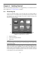
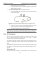
Table Of Contents
- Trademarks
- Copyright Information
- Disclaimer of Warranties and Limitation of Liabilities
- For Services and Support:
- Safety Information
- Contents
- Chapter 1 Using This Manual
- Chapter 2 General Introduction
- Chapter 3 Getting Started
- Chapter 4 Diagnostics Operations
- Chapter 5 Data Manager Operations
- Chapter 6 MaxiFix Operations
- 6.1 Navigation
- The Header
- Select Vehicle Button
- The “Select Vehicle” button on the Header allows you to specify the vehicle which you want to reference on MaxiFix, by selecting each of the vehicle attribute from a sequence of option lists. This feature helps to filter out the searches that allow on...
- 6.1.1 Terminology
- 6.2 Operations
- 6.1 Navigation
- Chapter 7 Settings Operations
- Chapter 8 Shop Manager Operations
- Chapter 9 Update Operations
- Chapter 10 VCI Manager Operations
- Chapter 11 Remote Desk Operations
- Chapter 12 Support Operations
- Chapter 13 Training Operations
- Chapter 14 Quick Link Operations
- Chapter 15 MaxiScope Operations
- 15.1 Safety Information
- 15.2 Glossary
- 15.3 MaxiScope Module
- 15.4 Screen Layout and Operations
- 15.4.1 Top Toolbar
- Math Channel
- A math channel is virtual channel generated by mathematical function of the input channel. It can be displayed in a scope or XY view in the same way as an input signal, and like an input signal it has its own measure axis, scaling and color. The MaxiS...
- Probe
- A probe is any transducer, measuring device or other accessory that you connect to an input channel of your MaxiScope module.
- Reference Waveform
- Recall Reference
- 15.4.2 Functional Buttons
- 15.4.3 Measurement Grid
- 15.4.4 Measurement Rulers
- 15.4.5 Functional Buttons
- 15.4.1 Top Toolbar
- 15.5 Troubleshooting
- 15.6 MaxiScope Firmware Update
- Chapter 16 Digital Inspection Operations
- Chapter 17 Maintenance and Service
- Chapter 18 Compliance Information
- Chapter 19 Warranty

20
Chapter 4 Diagnostics Operations
By establishing a data link to the electronic control systems of the vehicle being
serviced through the VCI device, the Diagnostics application allows you to retrieve
diagnostic information, view live data parameters, and perform active tests. The
Diagnostics application can access the electronic control module (ECM) for various
vehicle control systems, such as engine, transmission, antilock brake system (ABS),
airbag system (SRS) and more.
4.1 Establishing Vehicle Communication
The Diagnostics operations require connecting the MaxiSys/MaxiSys Pro
Diagnostic Platform to the test vehicle through the VCI device using the main
cable, and test adapters (for non-OBD II vehicles). To establish proper vehicle
communication to the MaxiSys display tablet, you need to perform the
following steps:
1. Connect the VCI device to the vehicle’s DLC for both communication and
power source.
2. Connect the VCI device to the MaxiSys display tablet via BT pairing, or
USB connection.
3. When these are done, check the VCI navigation button at the bottom bar
on the screen, if the button displays a green tick icon at the lower right
corner, the MaxiSys/MaxiSys Pro diagnostic platform is ready to start
vehicle diagnosis.
4.1.1 Vehicle Connection
The method used to connect the VCI device to a vehicle’s DLC depends on
the vehicle’s configuration as follows:
A vehicle equipped with an On-board Diagnostics Two (OBD II)
management system supplies both communication and 12-volt power
through a standardized J-1962 DLC.
A vehicle not equipped with an OBD II management system supplies
communication through a DLC connection, and in some cases supplies
12-volt power through the cigarette lighter receptacle or a connection to
the vehicle battery.