
User Manual
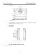
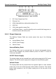

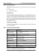
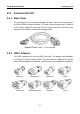
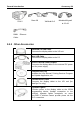
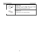
Table Of Contents
- Trademarks
- Copyright Information
- Disclaimer of Warranties and Limitation of Liabilities
- For Services and Support:
- Safety Information
- Contents
- Chapter 1 Using This Manual
- Chapter 2 General Introduction
- Chapter 3 Getting Started
- Chapter 4 Diagnostics Operations
- Chapter 5 Data Manager Operations
- Chapter 6 MaxiFix Operations
- 6.1 Navigation
- The Header
- Select Vehicle Button
- The “Select Vehicle” button on the Header allows you to specify the vehicle which you want to reference on MaxiFix, by selecting each of the vehicle attribute from a sequence of option lists. This feature helps to filter out the searches that allow on...
- 6.1.1 Terminology
- 6.2 Operations
- 6.1 Navigation
- Chapter 7 Settings Operations
- Chapter 8 Shop Manager Operations
- Chapter 9 Update Operations
- Chapter 10 VCI Manager Operations
- Chapter 11 Remote Desk Operations
- Chapter 12 Support Operations
- Chapter 13 Training Operations
- Chapter 14 Quick Link Operations
- Chapter 15 MaxiScope Operations
- 15.1 Safety Information
- 15.2 Glossary
- 15.3 MaxiScope Module
- 15.4 Screen Layout and Operations
- 15.4.1 Top Toolbar
- Math Channel
- A math channel is virtual channel generated by mathematical function of the input channel. It can be displayed in a scope or XY view in the same way as an input signal, and like an input signal it has its own measure axis, scaling and color. The MaxiS...
- Probe
- A probe is any transducer, measuring device or other accessory that you connect to an input channel of your MaxiScope module.
- Reference Waveform
- Recall Reference
- 15.4.2 Functional Buttons
- 15.4.3 Measurement Grid
- 15.4.4 Measurement Rulers
- 15.4.5 Functional Buttons
- 15.4.1 Top Toolbar
- 15.5 Troubleshooting
- 15.6 MaxiScope Firmware Update
- Chapter 16 Digital Inspection Operations
- Chapter 17 Maintenance and Service
- Chapter 18 Compliance Information
- Chapter 19 Warranty

General Introduction VCI – J2534 ECU Programming Device
9
1. DC Power Supply Input Port
2. Vehicle Data Connector
3. Vehicle LED
Flashes green when communicating with the vehicle’s system
IMPORTANT: Do not disconnect the reprogramming device while this status
light is on! If the flash reprogramming procedure is interrupted while the
vehicle’s ECU is blank or only partially programmed, the module may be
unrecoverable.
4. Connection LED
Illuminates solid green when properly connected with the display
tablet via the USB cable
Illuminates solid blue when connected with the display tablet via
wireless (BT) connection
5. Power LED
Illuminates solid green when powered on
Flashes red when system failure occurs
Illuminates amber automatically at power up when the device is
performing self-test procedure
6. USB Port
J2534 Reprogramming Capability
The J2534 ECU Programming Device is a SAE J2534-1 & -2 compliant
PassThru reprogramming interface device. Using the updated OEM software,
it is capable of replacing the existing software/firmware in the Electronic
Control Units (ECU), programming new ECUs and fixing software-controlled
drivability issues and emission issues.
Communication
The J2534 ECU programming device supports BT and USB communications.
It can transmit vehicle data to the MaxiSys display tablet with or without a
physical connection. The working range of the transmitter through BT
communication is 210 feet (about 70 m). A signal lost due to moving out of
range automatically restores itself when the display tablet unit is brought
closer to the VCI unit.