
User Manual
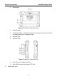
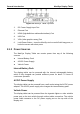

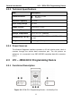
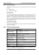
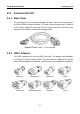
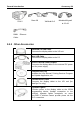

Table Of Contents
- Trademarks
- Copyright Information
- Disclaimer of Warranties and Limitation of Liabilities
- For Services and Support:
- Safety Information
- Contents
- Chapter 1 Using This Manual
- Chapter 2 General Introduction
- Chapter 3 Getting Started
- Chapter 4 Diagnostics Operations
- Chapter 5 Data Manager Operations
- Chapter 6 MaxiFix Operations
- 6.1 Navigation
- The Header
- Select Vehicle Button
- The “Select Vehicle” button on the Header allows you to specify the vehicle which you want to reference on MaxiFix, by selecting each of the vehicle attribute from a sequence of option lists. This feature helps to filter out the searches that allow on...
- 6.1.1 Terminology
- 6.2 Operations
- 6.1 Navigation
- Chapter 7 Settings Operations
- Chapter 8 Shop Manager Operations
- Chapter 9 Update Operations
- Chapter 10 VCI Manager Operations
- Chapter 11 Remote Desk Operations
- Chapter 12 Support Operations
- Chapter 13 Training Operations
- Chapter 14 Quick Link Operations
- Chapter 15 MaxiScope Operations
- 15.1 Safety Information
- 15.2 Glossary
- 15.3 MaxiScope Module
- 15.4 Screen Layout and Operations
- 15.4.1 Top Toolbar
- Math Channel
- A math channel is virtual channel generated by mathematical function of the input channel. It can be displayed in a scope or XY view in the same way as an input signal, and like an input signal it has its own measure axis, scaling and color. The MaxiS...
- Probe
- A probe is any transducer, measuring device or other accessory that you connect to an input channel of your MaxiScope module.
- Reference Waveform
- Recall Reference
- 15.4.2 Functional Buttons
- 15.4.3 Measurement Grid
- 15.4.4 Measurement Rulers
- 15.4.5 Functional Buttons
- 15.4.1 Top Toolbar
- 15.5 Troubleshooting
- 15.6 MaxiScope Firmware Update
- Chapter 16 Digital Inspection Operations
- Chapter 17 Maintenance and Service
- Chapter 18 Compliance Information
- Chapter 19 Warranty

General Introduction VCI – J2534 ECU Programming Device
8
2.2.2 Technical Specifications
Item
Description
Communications
BT V.2.1 + EDR
USB 2.0
Wireless Frequency
2.4 GHz
Input Voltage Range
12 VDC
Supply Current
200 mA @ 12 VDC
Operating Temperature
0°C to 50°C (ambient)
Storage Temperature
-20°C to 70°C (ambient)
Dimensions (L x W x H)
147.5 mm (5.80”) x 85.5 mm (3.37”) x 29.0 mm
(1.14”)
Weight
0.215 kg (0.473 lb.)
2.2.3 Power Sources
The Wireless Diagnostic Interface operates on 12-volt vehicle power, which it
receives through the vehicle data connection port. The unit powers on
whenever it is connected to an OBD II/EOBD compliant data link connector
(DLC).
2.3 VCI – J2534 ECU Programming Device
2.3.1 Functional Description
Figure 2-6 J2534 ECU Programming Device – for MaxiSys Pro