
User Manual
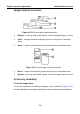
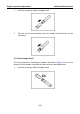
Table Of Contents
- Trademarks
- Copyright Information
- Disclaimer of Warranties and Limitation of Liabilities
- For Services and Support:
- Safety Information
- Contents
- Chapter 1 Using This Manual
- Chapter 2 General Introduction
- Chapter 3 Getting Started
- Chapter 4 Diagnostics Operations
- Chapter 5 Data Manager Operations
- Chapter 6 MaxiFix Operations
- 6.1 Navigation
- The Header
- Select Vehicle Button
- The “Select Vehicle” button on the Header allows you to specify the vehicle which you want to reference on MaxiFix, by selecting each of the vehicle attribute from a sequence of option lists. This feature helps to filter out the searches that allow on...
- 6.1.1 Terminology
- 6.2 Operations
- 6.1 Navigation
- Chapter 7 Settings Operations
- Chapter 8 Shop Manager Operations
- Chapter 9 Update Operations
- Chapter 10 VCI Manager Operations
- Chapter 11 Remote Desk Operations
- Chapter 12 Support Operations
- Chapter 13 Training Operations
- Chapter 14 Quick Link Operations
- Chapter 15 MaxiScope Operations
- 15.1 Safety Information
- 15.2 Glossary
- 15.3 MaxiScope Module
- 15.4 Screen Layout and Operations
- 15.4.1 Top Toolbar
- Math Channel
- A math channel is virtual channel generated by mathematical function of the input channel. It can be displayed in a scope or XY view in the same way as an input signal, and like an input signal it has its own measure axis, scaling and color. The MaxiS...
- Probe
- A probe is any transducer, measuring device or other accessory that you connect to an input channel of your MaxiScope module.
- Reference Waveform
- Recall Reference
- 15.4.2 Functional Buttons
- 15.4.3 Measurement Grid
- 15.4.4 Measurement Rulers
- 15.4.5 Functional Buttons
- 15.4.1 Top Toolbar
- 15.5 Troubleshooting
- 15.6 MaxiScope Firmware Update
- Chapter 16 Digital Inspection Operations
- Chapter 17 Maintenance and Service
- Chapter 18 Compliance Information
- Chapter 19 Warranty

Digital Inspection Operations Additional Accessories
125
1. Hold the accessory and the imager head.
2. Slip the end of the accessory over the imager head and then fix the
accessory.
For 5.5mm Imager Head
The two accessories, including the Magnet and Mirror (Figure 16-3), can be
attached to the Imager Head with the same manner described below:
1. Hold the accessory and the imager head.