
User Manual
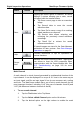
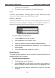
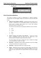
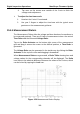
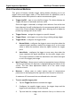
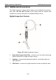
Table Of Contents
- Trademarks
- Copyright Information
- Disclaimer of Warranties and Limitation of Liabilities
- For Services and Support:
- Safety Information
- Contents
- Chapter 1 Using This Manual
- Chapter 2 General Introduction
- Chapter 3 Getting Started
- Chapter 4 Diagnostics Operations
- Chapter 5 Data Manager Operations
- Chapter 6 MaxiFix Operations
- 6.1 Navigation
- The Header
- Select Vehicle Button
- The “Select Vehicle” button on the Header allows you to specify the vehicle which you want to reference on MaxiFix, by selecting each of the vehicle attribute from a sequence of option lists. This feature helps to filter out the searches that allow on...
- 6.1.1 Terminology
- 6.2 Operations
- 6.1 Navigation
- Chapter 7 Settings Operations
- Chapter 8 Shop Manager Operations
- Chapter 9 Update Operations
- Chapter 10 VCI Manager Operations
- Chapter 11 Remote Desk Operations
- Chapter 12 Support Operations
- Chapter 13 Training Operations
- Chapter 14 Quick Link Operations
- Chapter 15 MaxiScope Operations
- 15.1 Safety Information
- 15.2 Glossary
- 15.3 MaxiScope Module
- 15.4 Screen Layout and Operations
- 15.4.1 Top Toolbar
- Math Channel
- A math channel is virtual channel generated by mathematical function of the input channel. It can be displayed in a scope or XY view in the same way as an input signal, and like an input signal it has its own measure axis, scaling and color. The MaxiS...
- Probe
- A probe is any transducer, measuring device or other accessory that you connect to an input channel of your MaxiScope module.
- Reference Waveform
- Recall Reference
- 15.4.2 Functional Buttons
- 15.4.3 Measurement Grid
- 15.4.4 Measurement Rulers
- 15.4.5 Functional Buttons
- 15.4.1 Top Toolbar
- 15.5 Troubleshooting
- 15.6 MaxiScope Firmware Update
- Chapter 16 Digital Inspection Operations
- Chapter 17 Maintenance and Service
- Chapter 18 Compliance Information
- Chapter 19 Warranty

Digital Inspection Operations MaxiScope Firmware Update
120
desired voltage point. The voltage info is displayed in a small
reference box.
4. Tap and slide the time base reference line left or right to the desired
point.
5. Tap Start button on the top right side of the screen to activate the
scope.
15.5 Troubleshooting
If the MaxiScope is not communicating with the MaxiSys display tablet, you
need to do the followings:
Check if the MaxiScope is properly connected to the MaxiSys display
tablet through the supplied USB cable.
If the MaxiScope is already connected to the MaxiSys display tablet, but
the communication between the devices has failed, tap the Scope Icon
on the top right side of the screen to reset the USB connection.
IMPORTANT: All vehicle communications must be terminated before resetting
the USB connection to avoid damage to the devices and the vehicle. The
Internet connection may be aborted during USB reset.
If the communication between the MaxiScope and the MaxiSys display
tablet still fails after USB reset, restart the MaxiSys display tablet and
reconnect the MaxiScope.
15.6 MaxiScope Firmware Update
The operating software of the MaxiScope is continuously being developed,
and the update package can be downloaded free from the MaxiScope product
webpage on Autel’s website: http://www.autel.com.
To update the MaxiScope firmware
1. Install the CD provided with the MaxiScope tool kit into the
CD-ROM of the computer. The installation wizard will load
momentarily.
2. Click on Next on the welcome page.
3. Click the Browse button, and select a destination folder to install
the program, and click Next to continue. Or directly click Next to
continue without changing the default installation folder.