
User Manual
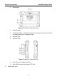

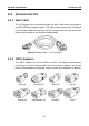
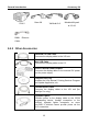
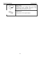
Table Of Contents
- Trademarks
- Copyright Information
- Disclaimer of Warranties and Limitation of Liabilities
- For Services and Support:
- Safety Information
- Contents
- Chapter 1 Using This Manual
- Chapter 2 General Introduction
- Chapter 3 Getting Started
- Chapter 4 Diagnostics Operations
- Chapter 5 Data Manager Operations
- Chapter 6 MaxiFix Operations
- 6.1 Navigation
- The Header
- Select Vehicle Button
- The “Select Vehicle” button on the Header allows you to specify the vehicle which you want to reference on MaxiFix, by selecting each of the vehicle attribute from a sequence of option lists. This feature helps to filter out the searches that allow on...
- 6.1.1 Terminology
- 6.2 Operations
- 6.1 Navigation
- Chapter 7 Settings Operations
- Chapter 8 Shop Manager Operations
- Chapter 9 Update Operations
- Chapter 10 VCI Manager Operations
- Chapter 11 Remote Desk Operations
- Chapter 12 Support Operations
- Chapter 13 Training Operations
- Chapter 14 Quick Link Operations
- Chapter 15 MaxiScope Operations
- 15.1 Safety Information
- 15.2 Glossary
- 15.3 MaxiScope Module
- 15.4 Screen Layout and Operations
- 15.4.1 Top Toolbar
- Math Channel
- A math channel is virtual channel generated by mathematical function of the input channel. It can be displayed in a scope or XY view in the same way as an input signal, and like an input signal it has its own measure axis, scaling and color. The MaxiS...
- Probe
- A probe is any transducer, measuring device or other accessory that you connect to an input channel of your MaxiScope module.
- Reference Waveform
- Recall Reference
- 15.4.2 Functional Buttons
- 15.4.3 Measurement Grid
- 15.4.4 Measurement Rulers
- 15.4.5 Functional Buttons
- 15.4.1 Top Toolbar
- 15.5 Troubleshooting
- 15.6 MaxiScope Firmware Update
- Chapter 16 Digital Inspection Operations
- Chapter 17 Maintenance and Service
- Chapter 18 Compliance Information
- Chapter 19 Warranty

General Introduction MaxiSys Display Tablet
5
Figure 2-4 MaxiSys Tablet Top View
1. DC Power Supply Input Port
2. Ethernet Port
3. HDMI (high-definition multimedia interface) Port
4. USB Port
5. VGA (video graphics array) Port
6. Lock/Power Button – turns the MaxiSys tool on and off with long press, or
locks the screen with short press
2.1.2 Power Sources
The MaxiSys Display Tablet can receive power from any of the following
sources:
Internal Battery Pack
AC/DC Power Supply
Vehicle Power
Internal Battery Pack
The display tablet can be powered with the internal rechargeable battery,
which if fully charged can provide sufficient power for about 7.5 hours of
continuous operation.
AC/DC Power Supply
The display tablet can be powered from a wall socket using the AC/DC power
adapter. The AC/DC power supply also charges the internal battery pack.
Vehicle Power
The display tablet can be powered from the cigarette lighter or other suitable
power port on the test vehicle through a direct cable connection. The vehicle
power cable connects to the DC power supply port on the top side of the
display unit.