
User Manual
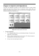
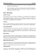
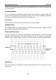
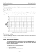
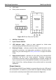
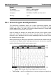
Table Of Contents
- Trademarks
- Copyright Information
- Disclaimer of Warranties and Limitation of Liabilities
- For Services and Support:
- Safety Information
- Contents
- Chapter 1 Using This Manual
- Chapter 2 General Introduction
- Chapter 3 Getting Started
- Chapter 4 Diagnostics Operations
- Chapter 5 Data Manager Operations
- Chapter 6 MaxiFix Operations
- 6.1 Navigation
- The Header
- Select Vehicle Button
- The “Select Vehicle” button on the Header allows you to specify the vehicle which you want to reference on MaxiFix, by selecting each of the vehicle attribute from a sequence of option lists. This feature helps to filter out the searches that allow on...
- 6.1.1 Terminology
- 6.2 Operations
- 6.1 Navigation
- Chapter 7 Settings Operations
- Chapter 8 Shop Manager Operations
- Chapter 9 Update Operations
- Chapter 10 VCI Manager Operations
- Chapter 11 Remote Desk Operations
- Chapter 12 Support Operations
- Chapter 13 Training Operations
- Chapter 14 Quick Link Operations
- Chapter 15 MaxiScope Operations
- 15.1 Safety Information
- 15.2 Glossary
- 15.3 MaxiScope Module
- 15.4 Screen Layout and Operations
- 15.4.1 Top Toolbar
- Math Channel
- A math channel is virtual channel generated by mathematical function of the input channel. It can be displayed in a scope or XY view in the same way as an input signal, and like an input signal it has its own measure axis, scaling and color. The MaxiS...
- Probe
- A probe is any transducer, measuring device or other accessory that you connect to an input channel of your MaxiScope module.
- Reference Waveform
- Recall Reference
- 15.4.2 Functional Buttons
- 15.4.3 Measurement Grid
- 15.4.4 Measurement Rulers
- 15.4.5 Functional Buttons
- 15.4.1 Top Toolbar
- 15.5 Troubleshooting
- 15.6 MaxiScope Firmware Update
- Chapter 16 Digital Inspection Operations
- Chapter 17 Maintenance and Service
- Chapter 18 Compliance Information
- Chapter 19 Warranty

MaxiScope Operations MaxiScope Module
110
USB Cable
Other probe accessories
Figure 15-3 Front, Rear, and Top View
1. USB Port Connector
2. Input Channel A/B/C/D
3. LED Indicator Light – lights up when powered on, blinks when
communicating, and shimmers when error occurs
4. Warning Triangle – indicates potential safety hazard that exists on the
indicated connections, and appropriate precautions should be taken.
Make sure you read through the Safety Information on page 105 before
using.
5. Equipotential Symbol – indicates the outer shells of the indicated BNC
connectors are all at the same potential. Therefore, necessary
precautions should be taken to avoid applying a potential through the
return connections of the indicated BNC terminals, as this may result in a
large current flow, causing damage to the product and the connected
equipment.
Power Source
The MaxiScope MP408 Scope Module is powered directly by the USB port of
the connected PC, no batteries or power leads are required, making it suitable
for use both for workshop-based and mobile automotive diagnostics.