
User Manual
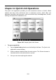
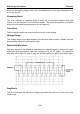
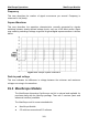
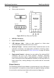
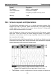
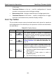
Table Of Contents
- Trademarks
- Copyright Information
- Disclaimer of Warranties and Limitation of Liabilities
- For Services and Support:
- Safety Information
- Contents
- Chapter 1 Using This Manual
- Chapter 2 General Introduction
- Chapter 3 Getting Started
- Chapter 4 Diagnostics Operations
- Chapter 5 Data Manager Operations
- Chapter 6 MaxiFix Operations
- 6.1 Navigation
- The Header
- Select Vehicle Button
- The “Select Vehicle” button on the Header allows you to specify the vehicle which you want to reference on MaxiFix, by selecting each of the vehicle attribute from a sequence of option lists. This feature helps to filter out the searches that allow on...
- 6.1.1 Terminology
- 6.2 Operations
- 6.1 Navigation
- Chapter 7 Settings Operations
- Chapter 8 Shop Manager Operations
- Chapter 9 Update Operations
- Chapter 10 VCI Manager Operations
- Chapter 11 Remote Desk Operations
- Chapter 12 Support Operations
- Chapter 13 Training Operations
- Chapter 14 Quick Link Operations
- Chapter 15 MaxiScope Operations
- 15.1 Safety Information
- 15.2 Glossary
- 15.3 MaxiScope Module
- 15.4 Screen Layout and Operations
- 15.4.1 Top Toolbar
- Math Channel
- A math channel is virtual channel generated by mathematical function of the input channel. It can be displayed in a scope or XY view in the same way as an input signal, and like an input signal it has its own measure axis, scaling and color. The MaxiS...
- Probe
- A probe is any transducer, measuring device or other accessory that you connect to an input channel of your MaxiScope module.
- Reference Waveform
- Recall Reference
- 15.4.2 Functional Buttons
- 15.4.3 Measurement Grid
- 15.4.4 Measurement Rulers
- 15.4.5 Functional Buttons
- 15.4.1 Top Toolbar
- 15.5 Troubleshooting
- 15.6 MaxiScope Firmware Update
- Chapter 16 Digital Inspection Operations
- Chapter 17 Maintenance and Service
- Chapter 18 Compliance Information
- Chapter 19 Warranty

MaxiScope Operations Safety Information
106
prevent personal injury or death, use a voltmeter to check that there is no
significant AC or DC voltage between the oscilloscope ground and the point
to which you intend to connect it.
WARNING:
Applying a voltage to the ground input is likely to cause permanent damage
to the oscilloscope, the attached computer, and other equipment.
To prevent measurement errors caused by poor grounding, always use the
high-quality USB cable supplied with the oscilloscope.
C. External connections
DANGER:
To prevent injury or death, use only the power cord and adaptor supplied
with the product.
D. Environment
DANGER:
To prevent injury or death, do not use in wet or damp conditions, or around
explosive gas or vapor.
WARNING:
To prevent damage, always use and store your oscilloscope in appropriate
environments. For detailed information on temperature and humidity
specifications for both the storage and usage of the oscilloscope, see 15.1
Safety Information on page 105.
E. Product Maintenance
The product contains no user-serviceable parts. Repair, servicing and calibration
require specialized test equipment and must only be performed by Autel Tech
Support or an approved service provider.
DANGER:
To prevent injury or death, do not use the product if it appears to be
damaged in any way, and stop use immediately if you are concerned by any
abnormal operations.
WARNING:
Do not tamper with or disassemble the oscilloscope, connectors or
accessories. Internal damage will affect performance