
User Manual

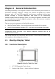
Table Of Contents
- Trademarks
- Copyright Information
- Disclaimer of Warranties and Limitation of Liabilities
- For Services and Support:
- Safety Information
- Contents
- Chapter 1 Using This Manual
- Chapter 2 General Introduction
- Chapter 3 Getting Started
- Chapter 4 Diagnostics Operations
- Chapter 5 Data Manager Operations
- Chapter 6 MaxiFix Operations
- 6.1 Navigation
- The Header
- Select Vehicle Button
- The “Select Vehicle” button on the Header allows you to specify the vehicle which you want to reference on MaxiFix, by selecting each of the vehicle attribute from a sequence of option lists. This feature helps to filter out the searches that allow on...
- 6.1.1 Terminology
- 6.2 Operations
- 6.1 Navigation
- Chapter 7 Settings Operations
- Chapter 8 Shop Manager Operations
- Chapter 9 Update Operations
- Chapter 10 VCI Manager Operations
- Chapter 11 Remote Desk Operations
- Chapter 12 Support Operations
- Chapter 13 Training Operations
- Chapter 14 Quick Link Operations
- Chapter 15 MaxiScope Operations
- 15.1 Safety Information
- 15.2 Glossary
- 15.3 MaxiScope Module
- 15.4 Screen Layout and Operations
- 15.4.1 Top Toolbar
- Math Channel
- A math channel is virtual channel generated by mathematical function of the input channel. It can be displayed in a scope or XY view in the same way as an input signal, and like an input signal it has its own measure axis, scaling and color. The MaxiS...
- Probe
- A probe is any transducer, measuring device or other accessory that you connect to an input channel of your MaxiScope module.
- Reference Waveform
- Recall Reference
- 15.4.2 Functional Buttons
- 15.4.3 Measurement Grid
- 15.4.4 Measurement Rulers
- 15.4.5 Functional Buttons
- 15.4.1 Top Toolbar
- 15.5 Troubleshooting
- 15.6 MaxiScope Firmware Update
- Chapter 16 Digital Inspection Operations
- Chapter 17 Maintenance and Service
- Chapter 18 Compliance Information
- Chapter 19 Warranty

3
Chapter 2 General Introduction
The MaxiSys
®
/MaxiSys
®
Pro Diagnostic Platform is an evolutionary smart solution for
specialized automotive diagnosis. Utilizing the powerful A9 quad-core 1.40GHz
processor, and a 9.7 inch LED capacitive touch screen, combined with the best
possible coverage of OE-level diagnostics, and based on the revolutionary
multitask-capable Android Operating system, the MaxiSys organizes information with
test instrumentation to help you diagnose symptoms, codes, and customer complaints
easily, quickly and efficiently.
There are two main components to the MaxiSys system:
MaxiSys Display Tablet – the central processor and monitor for the system
Vehicle Communication Interface (VCI) – the device for accessing vehicle data
NOTE: Autel provides two optional VCI devices for your choice. One is the J2534
Programming Device; the other is the Wireless Diagnostic Interface, both will be
introduced in this chapter.
This manual describes the construction and operation of these devices and how they
work together to deliver diagnostic solutions.
2.1 MaxiSys Display Tablet
2.1.1 Functional Description
Figure 2-1 MaxiSys Tablet Front View
1. 9.7” LED Capacitive Touch Screen
2. Ambient Light Sensor – detects ambient brightness