
User Manual
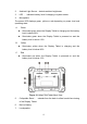
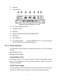


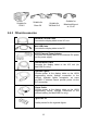
Table Of Contents
- Trademarks
- Copyright Information
- Disclaimer of Warranties and Limitation of Liabili
- For Services and Support:
- Safety Information
- Chapter 1 Using This Manual
- Chapter 2 General Introduction
- Chapter 3 Getting Started
- Chapter 4 Diagnostics Operations
- Chapter 5 Data Manager Operations
- Chapter 6 ADAS
- Chapter 7 MaxiFix Operations
- Chapter 8 Settings Operations
- Chapter 9 Shop Manager Operations
- Chapter 10 Update Operations
- Chapter 11 VCI Manager Operations
- Chapter 12 Remote Desk Operations
- Chapter 13 Support
- Chapter 14 Academy
- Chapter 15 Quick Link Operations
- Chapter 16 MaxiScope Operations
- Chapter 17 Function Viewer
- Chapter 18 Digital Inspection Operations
- Chapter 19 Maintenance and Service
- Chapter 20 Compliance Information
- Chapter 21 Warranty

12
2.4 Accessories Kit
2.4.1 Main Cable
The VCI device can be powered through the Main Cable when connected to
an OBD II/EOBD compliant vehicle. The Main Cable connects the VCI device
to the vehicle’s data link connector (DLC), through which the VCI device can
transmit vehicle data to the MaxiCOM display tablet.
Figure 2- 5 Main Cable – 1.5 m in length
2.4.2 OBD I Adapters
The OBD I adapters are for Non-OBD II vehicles. The adapter used depends
on the type of vehicle being tested. The most common adapters are shown
below (Some adapters are optional, please contact your distributor for details).
Suitable for
Benz-14
Suitable for
Chrysler-16
Suitable for
BMW-20
Suitable for
Kia-20
Suitable for
Nissan-14
Suitable for
GM/Daewoo-12
Suitable for
Honda-3
Suitable for Fiat-3