
User Manual


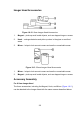


Table Of Contents
- Trademarks
- Copyright Information
- Disclaimer of Warranties and Limitation of Liabili
- For Services and Support:
- Safety Information
- Chapter 1 Using This Manual
- Chapter 2 General Introduction
- Chapter 3 Getting Started
- Chapter 4 Diagnostics Operations
- Chapter 5 Data Manager Operations
- Chapter 6 ADAS
- Chapter 7 MaxiFix Operations
- Chapter 8 Settings Operations
- Chapter 9 Shop Manager Operations
- Chapter 10 Update Operations
- Chapter 11 VCI Manager Operations
- Chapter 12 Remote Desk Operations
- Chapter 13 Support
- Chapter 14 Academy
- Chapter 15 Quick Link Operations
- Chapter 16 MaxiScope Operations
- Chapter 17 Function Viewer
- Chapter 18 Digital Inspection Operations
- Chapter 19 Maintenance and Service
- Chapter 20 Compliance Information
- Chapter 21 Warranty
114
16.4.5 Functional Buttons
This group of buttons includes trigger setting buttons allowing you to set
trigger source and trigger mode, a Time base button for adjustment, and a
Measurement button with options for various measurement types.
Trigger On/Off – taps to turn on/off the trigger. The button displays as
Trigger Off when it is activated, and vice versa.
Once the trigger is activated, a voltage scale reference line and a time
base reference line will be displayed on the measurement grid, the cross
point of the 2 lines indicates the trigger point, allowing users to adjust its
position by moving each of the 2 lines.
Trigger Source – assigns the trigger to a specific channel
Trigger Slope – sets trigger to occur by rising or falling voltage edges
Trigger Mode – configures the trigger mode:
A. Normal Mode – configures the trigger to occur every time when the
captured signal waveform reaches the trigger point, so the scope
starts to draw the waveform when the signal reaches the trigger
point.
B. Auto Mode – configures the trigger to occur every time when the
scope captures the signal waveforms by the preset trigger point.
The scope continues to draw the waveforms even when the signal
is not in the trigger point range.
Main Time Base – allows users to select an appropriate time per division.
The time per division (10 divisions) is displayed along the bottom of the
screen. The time base adjustment affects all of the active scope
channels at once.
Measure – allows users to select various types of measurement parameters
to be displayed at the right side of the screen for reference.
A maximum of 5 items each time are allowed to be selected.
To set a specific trigger point
1. Tap the Trigger On button to activate the trigger.
2. Configures the specific trigger source, the trigger slope and the
trigger mode according to the test demand.
3. Tap and slide the voltage scale reference line up or down to the