
User Manual

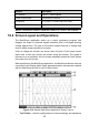

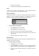


Table Of Contents
- Trademarks
- Copyright Information
- Disclaimer of Warranties and Limitation of Liabili
- For Services and Support:
- Safety Information
- Chapter 1 Using This Manual
- Chapter 2 General Introduction
- Chapter 3 Getting Started
- Chapter 4 Diagnostics Operations
- Chapter 5 Data Manager Operations
- Chapter 6 ADAS
- Chapter 7 MaxiFix Operations
- Chapter 8 Settings Operations
- Chapter 9 Shop Manager Operations
- Chapter 10 Update Operations
- Chapter 11 VCI Manager Operations
- Chapter 12 Remote Desk Operations
- Chapter 13 Support
- Chapter 14 Academy
- Chapter 15 Quick Link Operations
- Chapter 16 MaxiScope Operations
- Chapter 17 Function Viewer
- Chapter 18 Digital Inspection Operations
- Chapter 19 Maintenance and Service
- Chapter 20 Compliance Information
- Chapter 21 Warranty

113
4. Tap once on the screen area outside of the Y-axis to finish the
voltage scale adjustment.
To adjust the time base scale
1. Unselect the Y-axis if it’s activated.
2. Use your 2 fingers to adjust the time base with the typical zoom
gestures on the measurement grid area.
16.4.4 Measurement Rulers
The Measurement Rulers allow the voltage and time duration of a waveform to
be measured precisely. There are 2 kinds of measurement rulers: the vertical
Time Ruler and the horizontal Voltage Ruler.
Tap on the Ruler Activator on the bottom right corner of the measurement
grid and drag it across the screen to the desired position, a Time Ruler is
generated.
The Voltage Ruler can be generated in the similar way by clicking the Ruler
Activator on the top left corner and dragging it downwards.
When Measurement Rulers are generated, a Ruler Table showing time and
voltage values for the corresponding channels will be displayed. The Delta
icon refers to the absolute difference between the values of the 2 rulers, which
can be locked by tapping the Lock icon.
Figure 16- 8 Measurement Rulers Display