
User Manual

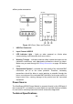
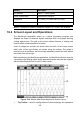

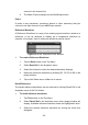


Table Of Contents
- Trademarks
- Copyright Information
- Disclaimer of Warranties and Limitation of Liabili
- For Services and Support:
- Safety Information
- Chapter 1 Using This Manual
- Chapter 2 General Introduction
- Chapter 3 Getting Started
- Chapter 4 Diagnostics Operations
- Chapter 5 Data Manager Operations
- Chapter 6 ADAS
- Chapter 7 MaxiFix Operations
- Chapter 8 Settings Operations
- Chapter 9 Shop Manager Operations
- Chapter 10 Update Operations
- Chapter 11 VCI Manager Operations
- Chapter 12 Remote Desk Operations
- Chapter 13 Support
- Chapter 14 Academy
- Chapter 15 Quick Link Operations
- Chapter 16 MaxiScope Operations
- Chapter 17 Function Viewer
- Chapter 18 Digital Inspection Operations
- Chapter 19 Maintenance and Service
- Chapter 20 Compliance Information
- Chapter 21 Warranty

112
16.4.3 Measurement Grid
The 2 control features – voltage per division and Time per division – enable
the users to adjust the scope settings to suit the particular test measurement.
Figure 16- 7 Sample Measurement Grid
Voltage per division – shown down the left side of the screen, referred to as
the Y-axis
Time per division – shown along the bottom of the screen, referred to as
the X-axis
Multiple Scope Channels
The MaxiScope software features multiple channel display which enables
more than one waveform to be displayed at the same time. It is useful for
making comparisons among different signals. The voltage per division for
each channel is adjusted individually while the time base per division is the
same for all channels.
To adjust the voltage scale
1. Tap the specific Y-axis of the corresponding channel to adjust. The
selected Y-axis is highlighted with thicker dividing line.
2. Adjust the voltage scale of the selected channel with the typical
2-finger zoom gestures.
3. The 0 volts is hinted with a pointer reference line. Slide the pointer
up and down to move and view different areas of the scale.