
User Manual

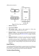
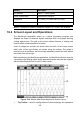
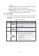

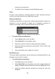


Table Of Contents
- Trademarks
- Copyright Information
- Disclaimer of Warranties and Limitation of Liabili
- For Services and Support:
- Safety Information
- Chapter 1 Using This Manual
- Chapter 2 General Introduction
- Chapter 3 Getting Started
- Chapter 4 Diagnostics Operations
- Chapter 5 Data Manager Operations
- Chapter 6 ADAS
- Chapter 7 MaxiFix Operations
- Chapter 8 Settings Operations
- Chapter 9 Shop Manager Operations
- Chapter 10 Update Operations
- Chapter 11 VCI Manager Operations
- Chapter 12 Remote Desk Operations
- Chapter 13 Support
- Chapter 14 Academy
- Chapter 15 Quick Link Operations
- Chapter 16 MaxiScope Operations
- Chapter 17 Function Viewer
- Chapter 18 Digital Inspection Operations
- Chapter 19 Maintenance and Service
- Chapter 20 Compliance Information
- Chapter 21 Warranty

111
4. Tap Yes and the selected reference waveform will appear on the
scope screen.
Figure 16- 6 Recall Reference Waveform Window
16.4.2 Functional Buttons
This group of buttons is used for configurations of channel activation,
measurement scale and trigger settings, the operations of which are described
below:
Channel Control Buttons A/B/C/D – tapping each button allows you to
activate or deactivate the corresponding channel; long pressing the
button opens a window, which allows you to select and configure
appropriate probes for specific tests.
The Channel Control Buttons are displayed in different colors as follows:
A. Red
B. Green
C. Blue
D. Pink
AC/DC Coupling and Voltage Scale Buttons – tapping this button opens a
dropdown menu, on which you can select AC or DC measurements and
adjust voltage measurement scales.
The Auto voltage scale option enables the scope to adjust the voltage
scale automatically to capture the signal.
AutoScale – tapping this button enables automatic set-up of the voltage
scale and time base for the signals received.
Start/Stop – tapping this button turns on/off the scope.
Single – tapping this button activates the Single trigger mode when the
trigger is on. The Single trigger mode configures the trigger to occur once
when the scope captures the first signal waveform by the preset trigger
point.