
User Manual

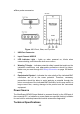
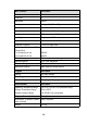
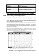

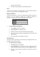


Table Of Contents
- Trademarks
- Copyright Information
- Disclaimer of Warranties and Limitation of Liabili
- For Services and Support:
- Safety Information
- Chapter 1 Using This Manual
- Chapter 2 General Introduction
- Chapter 3 Getting Started
- Chapter 4 Diagnostics Operations
- Chapter 5 Data Manager Operations
- Chapter 6 ADAS
- Chapter 7 MaxiFix Operations
- Chapter 8 Settings Operations
- Chapter 9 Shop Manager Operations
- Chapter 10 Update Operations
- Chapter 11 VCI Manager Operations
- Chapter 12 Remote Desk Operations
- Chapter 13 Support
- Chapter 14 Academy
- Chapter 15 Quick Link Operations
- Chapter 16 MaxiScope Operations
- Chapter 17 Function Viewer
- Chapter 18 Digital Inspection Operations
- Chapter 19 Maintenance and Service
- Chapter 20 Compliance Information
- Chapter 21 Warranty

107
General
Description
PC Interface
USB 2.0 – cable supplied
Power Requirements
Powered from USB port
Compliance
FCC (EMC), CE (EMC and LVD), RoHS
Warranty
1 year
NOTE*: Reduced to 20MS/s if channels A and B, or C and D, are enabled.
16.4 Screen Layout and Operations
The MaxiScope application works as a signal processing program that
displays the shape of electrical signals onscreen with a live graph showing
voltage against time. The grid on the screen shows divisions of voltage and
time to enable measurements to be made.
Units of voltage per division are shown down the side of the scope screen
while units of time per division are shown along the bottom. The graph is
referred to as a waveform and the scope repeatedly draws the trace across
the screen from left to right.
Before performing the MaxiScope application, the MaxiScope Module must be
connected to the display tablet. Apply appropriate probe accessories supplied
with the MaxiScope tool kit for use in various tests.
Figure 16- 4 Sample MaxiScope Application Screen Layout
1. Top Toolbar – used for configurations of various settings and operations