
User Manual

107
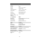
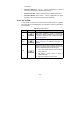
General Description
PC Interface USB 2.0 – cable supplied
Power Requirements Powered from USB port
Compliance FCC (EMC), CE (EMC and LVD), RoHS
Warranty 1 year
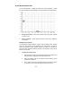
NOTE*: Reduced to 20MS/s if channels A and B, or C and D, are enabled.
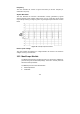
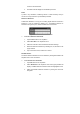
16.4 Screen Layout and Operations
The MaxiScope application works as a signal processing program that
displays the shape of electrical signals onscreen with a live graph showing
voltage against time. The grid on the screen shows divisions of voltage and
time to enable measurements to be made.
Units of voltage per division are shown down the side of the scope screen
while units of time per division are shown along the bottom. The graph is
referred to as a waveform and the scope repeatedly draws the trace across
the screen from left to right.
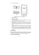
Before performing the MaxiScope application, the MaxiScope Module must be
connected to the display tablet. Apply appropriate probe accessories supplied
with the MaxiScope tool kit for use in various tests.
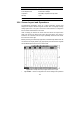
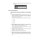
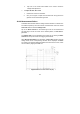
Figure 16- 4 Sample MaxiScope Application Screen Layout
1.
Top Toolbar – used for configurations of various settings and operations