
User manual

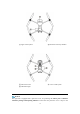


Table Of Contents
- Chapter 1
- About the Manual
- 1.1 Instructions for the first flight
- Chapter 2
- Be familiar with your smart UAV.
- 2.1 Aircraft
- 2.2 Remote controller
- Chapter 3
- Flight preparation
- 3.1 Battery preparation
- 3.2 Remote controller preparation
- 3.3 Aircraft preparation
- Chapter 4
- Flight Operation
- 4.1 Check list before flight
- 4.2 Flight operation
- 4.2.1 Motor start and aircraft takeoff (American m
- 4.2.2 Manipulator control (American manipulator)
- Chapter 5
- Maintenance and service
- 5.2 Solutions to common faults
- 5.3 Storage and maintenance
- 5.4 Warranty
- 5.5 Customer service
- Chapter 6
- Annex
- 6.1 Authentication information and restricted area
- 6.2 Specifications

13
closed state during flight.
2.1.2 Flight indicator
The aircraft has one LED indicator at the end of each arm. The front LED shows steady red to
help you to find the head direction. The rear LED shows the current flight status of aircraft. The
following table shows the meaning of each status indicator.
Designated symbol of indicator:
Designated symbol of color:
Slow flash: flash once every two seconds
R
Red
Quick flash: flash twice per second
G
Green
Alternate flash: alternate flash in different colors
Y
Yellow
Status definition of flight LED indicator
Normal status
RGY - alternate flash
System self-test
YG - alternate flash
Preheat
G - slow flash
Aircraft in GPS mode
Warning
Y - slow flash
Aircraft in ATTI mode
Y - rapid flash
No connection between aircraft and remote controller
R - slow flash
Low battery warning
R - quick flash
Serious low battery warning
R - Normally on
Serious problem or IMU abnormality
RY - alternate flash
Compass is abnormal, and needs to be
calibrated/magnetometer interference
Compass calibration
Y - rapid flash
Prepare for compass calibration/aircraft under calibration