
EVO Lite Series User Manual

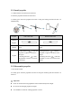


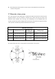
Table Of Contents
- User Manual
- EVO Lite Series
- Terms for Usage
- Trademark Information
- Copyright
- Disclaimer
- Data Storage and Use
- Table of contents
- Chapter 1 Read Instructions
- Chapter 2 Aircraft
- ① Propeller
- ④ Gimbal camera
- ② Undercarriage
- ⑤ Front LED indicator
- ③ Forward visual system
- ⑥ Motor
- ⑦ Power button
- ⑨ Rear LED indicator
- ⑧ Rear vision system
- ⑩ Air outlet
- ⑪ SD card slot
- ⑫ Aircraft battery
- ⑬ USB-C port
- ⑭ Ultrasonic sensor
- ⑯ Downward vision system
- ⑮ Downward LED
- The aircraft has one LED indicator at the end of e
- Designated symbol of color:
- R - Red
- Y - Yellow
- G - Green
- B - Blue
- Front LED Indicator
- Back LED Indicator
- Meaning
- B - Normally on
- G - Slow flash(2 secs/1 time)
- Aircraft in GPS mode
- B - Normally on
- Y - Slow flash(1 sec/1 time)
- Aircraft in ATTI mode
- B - Normally on
- Y - Slow flash(1 sec/1 time)
- Low battery warning
- B - Normally on
- R - Slow flash(1 sec/1 time)
- Serious low battery warning
- B - Normally on
- Y - Normally on
- Aircraft under calibration
- B - Normally on
- G - Normally on
- Calibration successful
- B - Normally on
- Y - Normally on
- Calibration failed
- B - Rapid flash
- G - Rapid flash
- Aircraft under pairing
- B - Rapid flash
- G - Normally on 5S
- Pairing successful
- B - Rapid flash
- R - Normally on 5S
- Pairing failed
- B - Rapid flash
- G - Rapid flash
- Aircraft under upgrading
- B - Normally on
- G - Normally on
- Upgrading successful
- B - Normally on
- Y - Slow flash(1 sec/1 time)
- Upgrading failed
- The battery for EVO Lite is 6175mAh and has the ra
- The battery indicator is divided into LED 1, LED
- Chapter 3 Remote controller
- Chapter 4 Autel Sky App
- When shooting night scene videos, users can choose
- Standard: The shooting effect is the same as the n
- Night: it will automatically adjust the ISO value,
- Super Night: it will automatically adjust the ISO
- Chapter 5 Flight
- 1) As shown in figure, press the left and right st
- 2) Slowly push up the left stick.
- 1) Press and slide the one-click takeoff button (
- 2) The aircraft will automatically rise to the hei
- Class I: main airport & low-altitude area for mann
- Class II: Sensitive area or organization & militar
- Chapter 6 Maintenance and service
- Method 1: download firmware upgrade package from A
- Method 2: download firmware upgrade package from t
- Chapter 7 Technical Specification

Please keep away from the metal or electric object, and maintain the aircraft at about
1.5m above the ground.
2.7 Binocular vision system
The vision system use the image data to calculate the distance between the aircraft and the
potential obstacles. Once any obstacle is detected, the system will stop the aircraft. The
ultrasonic sensor modules (one receiving, one transmitting) are also installed below the
aircraft to provide the reference height of the aircraft above the ground and cooperate with the
vision system to calculate the position information of the aircraft.
Binocular vision system
System
Position on aircraft
Sensing range
of obstacle
Viewing angle
Forward
The front of the aircraft
0.5 ~ 18 m
Horizontal< 70°, vertical< 88°
Backward
The tail of the aircraft
0.5 ~ 18 m
Horizontal< 40°, vertical< 30°
Downward
The bottom of the aircraft
0.5 ~ 22 m
Horizontal< 40°, vertical< 30°
The figure below shows the covering angle of each binocular vision system: