
User's Manual
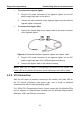
Table Of Contents
- Trademarks
- Copyright Information
- Disclaimer of Warranties and Limitation of Liabilities
- For Services and Support:
- Safety Information
- Contents
- Chapter 1 Using This Manual
- Chapter 2 General Introduction
- Chapter 3 Getting Started
- Chapter 4 Diagnostics Operations
- Chapter 5 Data Manager Operations
- Chapter 6 MaxiFix Operations
- Chapter 7 Settings Operations
- Chapter 8 Shop Manager Operations
- Chapter 9 Update Operations
- Chapter 10 VCI Manager Operations
- Chapter 11 Remote Desk Operations
- Chapter 12 Support Operations
- Chapter 13 Training Operations
- Chapter 14 Quick Link Operations
- Chapter 15 Digital Inspection Operations
- Chapter 16 Maintenance and Service
- Chapter 17 Compliance Information
- Chapter 18 Warranty

Diagnostics Operations Establishing Vehicle Communication
To connect the cigarette lighter
1. Plug the DC power connector of the cigarette lighter into the DC
power supply input port on the device.
2. Connect the male connector of the cigarette lighter into the vehicle’s
cigarette lighter receptacle.
To connect the clipper cable
1. Connect the tubular plug of the clipper cable to the male connector
of the cigarette lighter.
Figure 4-1 Connection between Cigarette Lighter and Clipper Cable
2. Plug the DC power connector of the cigarette lighter into the DC
power supply input port of the J2534 programming device.
3. Connect the clipper cable to the vehicle’s battery.
NOTE: After the VCI device is successfully connected to the vehicle, the
Power LED on the device illuminates, and a brief beep sound will be heard.
4.1.2 VCI Connection
After the VCI device is properly connected to the vehicle, the Power LED on
the VCI device illuminates solid green light, and is ready to establish
communication with the MaxiSys display tablet.
The J2534 ECU Programming Device, which comes with the MaxiSys Elite
tool kit, supports 3 communication methods with the MaxiSys display tablet:
Bluetooth, USB, and Ethernet connection.
21