
User's Manual
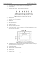
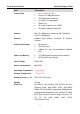
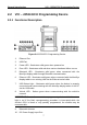
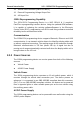
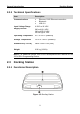
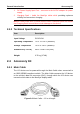
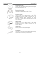
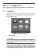
Table Of Contents
- Trademarks
- Copyright Information
- Disclaimer of Warranties and Limitation of Liabilities
- For Services and Support:
- Safety Information
- Contents
- Chapter 1 Using This Manual
- Chapter 2 General Introduction
- Chapter 3 Getting Started
- Chapter 4 Diagnostics Operations
- Chapter 5 Data Manager Operations
- Chapter 6 MaxiFix Operations
- Chapter 7 Settings Operations
- Chapter 8 Shop Manager Operations
- Chapter 9 Update Operations
- Chapter 10 VCI Manager Operations
- Chapter 11 Remote Desk Operations
- Chapter 12 Support Operations
- Chapter 13 Training Operations
- Chapter 14 Quick Link Operations
- Chapter 15 Digital Inspection Operations
- Chapter 16 Maintenance and Service
- Chapter 17 Compliance Information
- Chapter 18 Warranty

General Introduction Accessory Kit
1. DC Power Supply Input Port – connects to the AC/DC adapter for power
supply
2. Charging Dock – holds the MaxiSys tablet while providing optimum
visibility and convenient charging
NOTE: Please make sure no small metal or other conductive parts are around
the Charging Dock to avoid short circuit damage to the device.
2.3.2 Technical Specifications
Item Description
Input Voltage
DC/12V/3A
Operating Temperature
-10°C to +55°C (ambient)
Storage Temperature
-40°C to +85°C (ambient)
Dimensions (L x W x H)
326.5 x 128.5 x 49 (mm)
Weight
0.79 kg (1.74lb)
2.4 Accessory Kit
2.4.1 Main Cable
The VCI device can be powered through the Main Cable when connected to
an OBD II/EOBD compliant vehicle. The Main Cable connects the VCI device
to the vehicle’s data link connector (DLC), through which the VCI device can
transmit vehicle data to the MaxiSys display tablet.
Figure 2-6 Main Cable – 1.5 m in length
10