
User's Manual
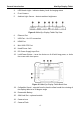
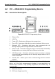
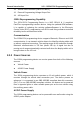
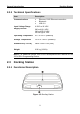
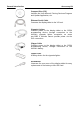
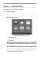
Table Of Contents
- Trademarks
- Copyright Information
- Disclaimer of Warranties and Limitation of Liabilities
- For Services and Support:
- Safety Information
- Contents
- Chapter 1 Using This Manual
- Chapter 2 General Introduction
- Chapter 3 Getting Started
- Chapter 4 Diagnostics Operations
- Chapter 5 Data Manager Operations
- Chapter 6 MaxiFix Operations
- Chapter 7 Settings Operations
- Chapter 8 Shop Manager Operations
- Chapter 9 Update Operations
- Chapter 10 VCI Manager Operations
- Chapter 11 Remote Desk Operations
- Chapter 12 Support Operations
- Chapter 13 Training Operations
- Chapter 14 Quick Link Operations
- Chapter 15 Digital Inspection Operations
- Chapter 16 Maintenance and Service
- Chapter 17 Compliance Information
- Chapter 18 Warranty

General Introduction VCI – J2534 ECU Programming Device
2.2 VCI – J2534 ECU Programming Device
2.2.1 Functional Description
Figure 2-4 J2534 ECU Programming Device
1. Ethernet Port
2. USB Port
3. Power LED - illuminates solid green when powered on
4. Error LED - illuminates solid red when serious hardware failure occurs
5. Bluetooth LED - illuminates solid green when connected with the
MaxiSys display tablet through Bluetooth communication
6. Ethernet LED - illuminates solid green when connected with the MaxiSys
display tablet or an existing LAN via the Ethernet serial cable
7. USB Status Light - illuminates solid green when the device is properly
connected and communicating with the MaxiSys display tablet or the PC
via the USB cable
8. Vehicle LED - flashes green when communicating with the vehicle’s
network
IMPORTANT: Do not disconnect the reprogramming device while this status
light is on! If the flash reprogramming procedure is interrupted while the
vehicle’s ECU is blank or only partially programmed, the module may be
unrecoverable.
9. Bluetooth Antenna
10. DC Power Supply Input Port
7