
User's Manual
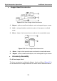
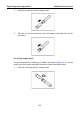
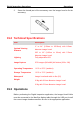
Table Of Contents
- Trademarks
- Copyright Information
- Disclaimer of Warranties and Limitation of Liabilities
- For Services and Support:
- Safety Information
- Contents
- Chapter 1 Using This Manual
- Chapter 2 General Introduction
- Chapter 3 Getting Started
- Chapter 4 Diagnostics Operations
- Chapter 5 Data Manager Operations
- Chapter 6 MaxiFix Operations
- Chapter 7 Settings Operations
- Chapter 8 Shop Manager Operations
- Chapter 9 Update Operations
- Chapter 10 VCI Manager Operations
- Chapter 11 Remote Desk Operations
- Chapter 12 Support Operations
- Chapter 13 Training Operations
- Chapter 14 Quick Link Operations
- Chapter 15 Digital Inspection Operations
- Chapter 16 Maintenance and Service
- Chapter 17 Compliance Information
- Chapter 18 Warranty

Digital Inspection Operations Operations
2. Screw the thread part of the accessory over the imager head to fix the
accessory.
15.2 Technical Specifications
Item Description
Optimal Viewing
Distance
1" to 14"
(2.54cm to 35.56cm) with 8.5mm
diameter imager head
3/8" to 12"
(0.95cm to 30cm) with 5.5mm
diameter imager head
Lighting Fully adjustable LED
Image Capture JPG images (640x480) AVI videos (320 x 240)
Operating Temperature
-10°C to 55°C (ambient)
Storage Temperature -20°C to 70°C (ambient)
Waterproof Imager head and cable to 3m (10')
Weight
0.3kg with 8.5mm diameter imager head
0.2kg with 5.5mm diameter imager head
15.3 Operations
Before performing the Digital Inspection application, the Imager Head Cable
must be connected to the MaxiSys display tablet through the USB port. Install
the correct imager head accessories for use in the appropriate application.
116