Table of Contents General Notice ........................................................... 1 Introduction .............................................................. 2 Functional Description .............................................. 4 Product Troubleshooting .......................................... 7 Driver Setup .............................................................. 8 Firmware Update ..................................................... 11 Compliance Information ........................
General Notice The Wireless Diagnostic Interface has been carefully designed and tested to comply with OBDII protocols. However, some vehicle models are not in full compliance with these protocols for various reasons. In addition, the computer control systems or sensors on any given vehicle may be malfunctioning.
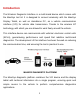
Introduction The Wireless Diagnostic Interface is a multi-brand device which comes with the MaxiSys tool kit. It is designed to connect wirelessly with the MaxiSys Display Tablet, as well as standalone PC, as a vehicle communication interface (VCI) for vehicle data transmission. Thanks to the wireless BT technology, with which you are allowed to work freely around the vehicle.
Wireless Communication The Wireless Diagnostic Interface supports BT communication. It can transmit vehicle data to the MaxiSys Display Tablet without a physical connection. The working range of the transmitter through BT communication is about 755 feet (about 230 m). A signal lost due to moving out of range automatically restores itself when the display unit is brought closer to the VCI unit.
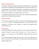
Functional Description The Wireless Diagnostic Interface device package, which includes the unit, user manual, and a CD with driver program and update agent, comes along with the MaxiSys/MaxiSys Mini tool kit. Please refer to the MaxiSys User Manual for additional information. 1. Vehicle Data Connector (DB15-Pin) 2. Power LED 3. Vehicle LED 4. Error LED 5. BT LED 6. USB LED 7.
Status LEDs There are 5 status LEDs on the front panel of the VCI device, which indicates its working status as well as the hardware conditions, and are very useful for troubleshooting the device’s communication or connection to the Vehicle, display tablet and/or the PC. See Table 1 for detailed description of the status LEDs. Table 1 – Status LEDs on the Front Panel LED Description Power Illuminates solid green when powered on. Vehicle Flashes green when communicating with the vehicle’s network.
Technical Specifications Item Description Communications BT V.2.1 + EDR USB 2.0 Wireless Frequency 2.4 GHz Input Voltage Range 12 VDC Supply Current 200 mA @ 12 VDC Operating Temperature 0°C to 50°C (ambient) Storage Temperature -20°C to 70°C (ambient) Dimensions (L x W x H) 147.5 mm (5.80”) x 85.5 mm (3.37”) x 29.0 mm (1.14”) Weight 0.208 kg (0.
Product Troubleshooting This part describes problems that you may encounter while using the VCI device. Vehicle Linking Error A communication error occurs if the interface device fails to communicate with the vehicle’s control module when performing diagnostic procedures. You need to do the following check-ups: Verify that the ignition is ON. Check if the interface device’s OBD II connector is securely connected to the vehicle’s DLC. Turn the ignition off and wait for about 10 seconds.
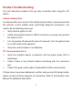
Driver Setup In order for the Wireless Diagnostic Interface device to operate correctly with the diagnostic applications on the PC, you will need to first install the device’s driver onto the PC that controls the device. The program package requires Windows XP, Windows 7 (32-bit or 64-bit), or Windows 8 (32-bit or 64-bit), or Windows 10 (32-bit or 64-bit) IMPORTANT: Do not plug the interface device onto the PC until you have installed the driver program.
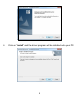
6 Click on “Install” and the driver program will be installed onto your PC.
NOTE: During this part of the process a MS-DOS style window will pop up and may remain on your screen for a short while, which is perfectly normal. Do not attempt to close the MS-DOS style window manually as this will prevent the device driver being installed successfully. It will close automatically when the device driver installation is complete. 7 When the driver is successfully installed, a confirm window will appear. Click on “Finish” to complete the whole installation procedure.
Firmware Update Autel periodically releases updates to the device’s drivers. Updates are necessary to solve specific problems and to ensure the VCI device is working properly with the OEM software. If you are experiencing any problems during use, always make sure that you have the latest device software and drivers. Update Online This function allows you to update the driver software for the device through the PC. Make sure the PC is connected to the Internet before using this function.
4 The update agent will automatically check for the available update online. 5 Press the “Next” button to install the newest firmware. 6 Press the “Cancel” button to exit.
Compliance Information FCC COMPLIANCE FCC ID: WQ82015BTDIAG This device complies with Part 15 of the FCC Rules. Operation is subject to the following two conditions: (1) This device may not cause harmful interference, and (2) this device must accept any interference received, including interference that may cause undesired operation. Warning: Changes or modifications not expressly approved by the party responsible for compliance could void the user's authority to operate the equipment.
outlet on a circuit different from that to which the receiver is connected. ⅳ. Consult the dealer or an experienced radio/TV technician for help. FCC Radiation Exposure Statement: This equipment complies with FCC radiation exposure limits set forth for an uncontrolled environment. This equipment should be installed and operated with minimum distance 20cm between the radiator & your body. RoHS COMPLIANCE This device is declared to be in compliance with the European RoHS Directive 2011/65/EU.
Warranty And Service Limited One Year Warranty Autel warrants to its customers that this product will be free from all defects in materials and workmanship for a period of one (1) year from the date of the original purchase, subject to the following terms and conditions: 1) 2) 3) 4) The sole responsibility of Autel under the Warranty is limited to either the repair or, at the option of Autel, replacement of the device at no charge with Proof of Purchase.