
User's Manual


- 13 -
LIPROMA3-00
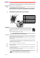
- 13 Radio frequencies -
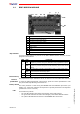
Module
calibration Position 0: dither frequency (for PWM output only)
When the rotary switch S is at 0, the PWM (current) dither frequency can be adjusted.
This value should not normally be modified. If necessary operate on the RPM+/- se-
lector on the transmitting unit to modify the desired value
Position 1: minimum and maximum values for Z2-Z7 outputs
The maximum and minimum values of the two semiaxis of each joystick are adjusted
with the rotary switch S in position 1. Proceed as follows:
- To set the maximum value, take the joystick to the maximum range of the semi-
axis to be calibrated. Keep the same position and use the toggle switch RPM +/-
to set the desired value.
- Once the maximum values have been set, take the joystick just out of the stand-
still position of the semiaxis to be calibrated to set the minimum values. Keep the
same position and use the toggle switch RPM +/- to set the desired value.
Position 2: output value when the joystick is in the standstill position
The voltage value corresponding to the joystick standstill position is adjusted with the
rotary switch S in position 2. This value should not normally be modified. If necessary
proceed as follows:
- take any joystick out of the standstill position
- Keep the same position and use the toggle switch RPM +/- to set the desired val-
ue.
Position 3: maximum and minimum Z8 output values
Position 4: maximum and minimum Z9 output values
When the rotary switch S is at 3 and 4, it is possible to regulate the maximum and
minimum values of auxiliary outputs Z8 and Z9 respectively. Proceed as follows:
- To fix the maximum value, use the related actuator (on the transmitting unit) and
take it to its end limit. Keep the same position and use the RPM +/- toggle switch
to set the desired value.
- Once the maximum value has been set, use the related actuator (on the trans-
mitting unit) and take it to the beginning to fix the minimum value. Keep the
same position and use the toggle switch RPM +/- to set the desired value.
Position 5: inversion of the movement direction
The direction of the movement is inverted with the rotary switch S in position 5 (for
the powered outputs only). Proceed as follows:
- position the joystick of the axis to be inverted outside the standstill position
- keep this position and position the RPM+/- selector on the transmitting unit to +
to invert the direction of the semiaxis, and to - to reset the semiaxis direction.
Saving the
calibration 9. Switch off the transmitting unit to save the calibration.
10. Remove power from the receiving unit.
11. Position DIP 1 to OFF.
12. Close the receiving unit and connect the power supply.
13
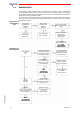
RADIO FREQUENCIES
A radio remote control can be programmed in AUTOMATIC SCAN or MANUAL SELEC-
TION.
Automatic
scan A radio remote control is normally programmed by the manufacturer in the following
manner: it can therefore operate in any of the available frequencies. In cases of in-
terference or conflict with other systems, the working frequency can be changed (see
paragraph “Frequency change”) without having to touch the inside of either the trans-
mitting or the receiving units.
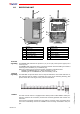
Manual
selection Only contact Autec authorized personnel if the working radio fre-
quency has to be set in this manner.
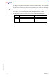
Using the radio remote control in the manual selection mode makes it possible to
work at a specific frequency. To set this frequency, you must set the dip switches lo-
cated in the transmitting and receiving modules.