
User's Manual


- 7 -
LIPROMA3-00
- 9 Transmitting unit and how it works -
Once all necessary checks have taken place, the installer must undersign the techni-
cal data sheet, which must be kept with the user's manual (always keep a copy of this
data sheet in case it could be required).
Identification
plates The radio remote control identification data are written on a technical data plate both
on the transmitting unit and on the receiving unit.
The plates MUST NOT be removed from where they are placed. If damaged,
please contact Autec or an authorized representative for a replacement.
9
TRANSMITTING UNIT AND HOW IT WORKS
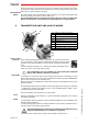
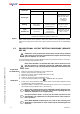
Power on and
start up Check that the starting keyswitch is in position “O”, gently insert the bat-
tery in its housing. Check that the STOP pushbutton has not been pressed
and that none of the actuators are out of their respective neutral posi-
tions.
Turn the starting keyswitch to “I”, activate the START pushbutton and re-
lease it when the green light starts to flash.
The transmitting unit only switches on if the battery has sufficient
charge and if all the actuators are inactive.
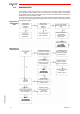
Commands
It is possible to control the radio remote machine only after the transmitting unit has
been radio linked to the receiving unit (signalled by the lighting up of the ENABLE pilot
light on the receiving unit (see chapter 10)).
After the radio link is established, machine movements are available by acting on the
proper actuators.
All commands protected by the SAFETY function are approved to category 3 of EN 954
- 1 against the undesired movements when in the standstill position (UMFS - Unin-
tended Movement From Standstill).
Some transmitting unit commands are given below:
Horn
With the transmitting unit switched on, press the START pushbutton: the machine
horn/alarm activates.
STOP
To immediately stop the machine, press the STOP pushbutton: the transmitting unit
switches off automatically.
To start working again, rotate the STOP pushbutton in the direction indicated and re-
peat the power on and start up procedures.
The STOP pushbutton must be used each time the machine has to be
stopped immediately due to a dangerous situation.
The STOP circuit is approved in category 4 according to the EN 954 -1.
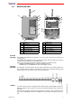
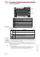
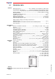
A
actuators (joystick or selector)
B
STOP pushbutton
C
START/horn pushbutton
D
starting keyswitch
E
selector rpm +/-
F
speed selector
G
battery
H
identification plate
L
two signalling LEDs (green and red)
A
E
F
C
D
L
H
G
B