
User's Manual


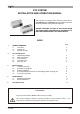
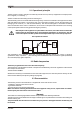
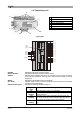
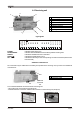
Table Of Contents
- Pagina 1
- Pagina 2
- Pagina 3
- Pagina 4
- Pagina 5
- Pagina 6
- Pagina 7
- Pagina 8
- Pagina 9
- Pagina 10
- Pagina 11
- Pagina 12
- Pagina 13
- Pagina 14
- Pagina 15
- Pagina 16
- Pagina 17
- Pagina 18
- Pagina 19
- Pagina 20
- Pagina 21
- Pagina 22
- Pagina 23
- Pagina 24
- Pagina 25
- Pagina 26
- Pagina 27
- Pagina 28
- Pagina 29
- Pagina 30
- Pagina 31
- Pagina 32
- Pagina 33
- Pagina 34
- Pagina 35
- Pagina 36

LIKTCNA0 Page 5
2.5 Receiving unit
Light signals
POWER:
STOP/ENABLE:
SAFETY:
START/ :
RL1 - RL14:
Additional command unit
Six commands may be added to those already incorporated in the receiving unit, by means of an additional
command unit.
To connect the additional command unit to the receiving unit:
- remove the cover on the bottom right (see photo)
- insert the extension connection cable into the connector on the receiving unit (see photo)
D
M
additional
command
unit
indicates power supply is on
indicates radio link between the transmitting and the receiving units
Indicates the SAFETY function is activated
indicates the START function is on
indicates that the relay for the corresponding command is activated (see the KTC
technical card)
A
H
B
C
D
F
L
G
STOP/ENA
POWER
START/
SAFETY
RL 1
RL 2
RL 3
RL 4
RL 5
RL 6
RL 7
RL 8
RL 9
RL 10
RL 11
RL 12
RL 13
RL 14
A Power supply terminal block
B Technical data plate
C Identification plate
D Output terminal blocks
F Openable cover
G Antenna connector
H Fuses
L Light signals
D Output terminal blocks
M Connection cable