
User's Manual


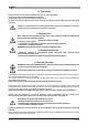
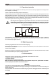
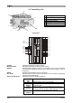
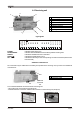
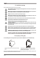
Table Of Contents
- Pagina 1
- Pagina 2
- Pagina 3
- Pagina 4
- Pagina 5
- Pagina 6
- Pagina 7
- Pagina 8
- Pagina 9
- Pagina 10
- Pagina 11
- Pagina 12
- Pagina 13
- Pagina 14
- Pagina 15
- Pagina 16
- Pagina 17
- Pagina 18
- Pagina 19
- Pagina 20
- Pagina 21
- Pagina 22
- Pagina 23
- Pagina 24
- Pagina 25
- Pagina 26
- Pagina 27
- Pagina 28
- Pagina 29
- Pagina 30
- Pagina 31
- Pagina 32
- Pagina 33
- Pagina 34
- Pagina 35
- Pagina 36

LIKTCNA0Page 4
2.4 Transmitting unit
Light signals
POWER:
STOP1 e STOP2:
SAFETY:
START:
RL1 - RL20:
State of the unit signal:
A
B
C
D
E
F
G
E
indicates that the power supply is present
indicates that the STOP circuit is working correctly
indicates that the SAFETY function is on (it must be on if any of the movement
commands are operational, when the unit is being used to operate or start up
equipment).
indicates that the START function is operational
indicates that the function which corresponds to the command is operational
(see KTC technical data sheet)
indicates the following operating conditions
RL
RL
RL
RL
RL
RL
RL
RL
RL
1
11
2
12
3
13
4
14
5
RL
RL
RL
RL
RL
RL
RL
RL
RL
15
6
16
7
17
8
18
9
19
RL
RL
10
20
SERIAL
NUMBER
Leggere il manuale d’uso.
Attenersi alle norme di sicurezza.
Togliere l’alimentazione in caso di apertura.
Read the user manual.
Adhere to safety rules.
Disconnet power source before opening.
Gebrauchsanleitung lesen.
Sicherheitsnormen beachten.
Die Speisespannung muss ausgeschaltet
werden, falls der Empfänger geöffnet wird.
Lire le manuel de l’utilisateur.
Respecter le consignes de sécurité.
Couper l’alimentation avant d’ouvrir le boîtier.
Leer el manual de uso.
Atenerse a las normas de seguridad.
Desconectar la alimentación antes de abrir.
!!
TRANSMITTER
ON
LOW VOLTAGE
STOP2
SAFETY
START
STOP1
POWER
State
of the unit
signal
A Power supply terminal block
B Technical data plate
C Identification plate
D Input terminal blocks
E Light signals
F Openable cover
G Antenna connector
Signal
State
Meaning
Off The transmitting unit is not transmitting
Slow
flashing
The transmitting unit is transmitting and the power
supply is correct.
Fast
flashing
The transmitting unit is transmitting but the power sup-
ply is not inside the correct voltage range (after about
3,5 minutes the unit will switch off automatically)
On not
flashing
Indicates that there are actuators inserted during start
up