
User's Manual
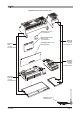
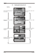
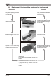
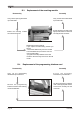
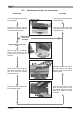
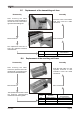
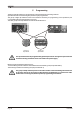
Table Of Contents
- Pagina 1
- Pagina 2
- Pagina 3
- Pagina 4
- Pagina 5
- Pagina 6
- Pagina 7
- Pagina 8
- Pagina 9
- Pagina 10
- Pagina 11
- Pagina 12
- Pagina 13
- Pagina 14
- Pagina 15
- Pagina 16
- Pagina 17
- Pagina 18
- Pagina 19
- Pagina 20
- Pagina 21
- Pagina 22
- Pagina 23
- Pagina 24
- Pagina 25
- Pagina 26
- Pagina 27
- Pagina 28
- Pagina 29
- Pagina 30
- Pagina 31
- Pagina 32
- Pagina 33
- Pagina 34
- Pagina 35
- Pagina 36

LIKTCNA0 Page 25
B.8 Replacement of the receiving unit fuses
Disassembly
After removing the cable
connectors, push the fuse to be
replaced with a screwdriver and
turn it in the indicated direction.
Assembly
Push the fuse rolling it in the
opposite direction to that
indicated. Insert the cable
connectors.
Remove the fuse.
Put in a new fuse.
The replacement fuse has to have
the technical characteristics
indicated in the following table:
B.7 Replacement of the transmitting unit fuse
Disassembly
After removing the cable
connectors, use a screwdriver to
remove the cover to the bottom
right of the transmitting unit.
Assembly
Close the cover to the bottom
right and insert the cable
connectors.
Remove the fuse.
Put in a new fuse.
The replacement fuse has to
have the indicated technical
characteristics:
Fuse Function Technical
characteristics
FUSE POWER SUPPLY 0.4A T 250V 5x20 mm
Fuse Function
Technical
characteristics
F1 POWER SUPPLY 1A T 250V 5x20 mm
F2 SAFETY 4A T 250V 5x20 mm
F3 STOP 4A T 250V 5x20 mm
F4 SAFETY 4A T 250V 5x20 mm