
User's Manual
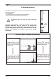
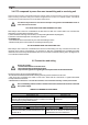
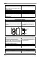

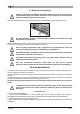
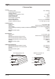

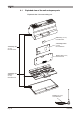
Table Of Contents
- Pagina 1
- Pagina 2
- Pagina 3
- Pagina 4
- Pagina 5
- Pagina 6
- Pagina 7
- Pagina 8
- Pagina 9
- Pagina 10
- Pagina 11
- Pagina 12
- Pagina 13
- Pagina 14
- Pagina 15
- Pagina 16
- Pagina 17
- Pagina 18
- Pagina 19
- Pagina 20
- Pagina 21
- Pagina 22
- Pagina 23
- Pagina 24
- Pagina 25
- Pagina 26
- Pagina 27
- Pagina 28
- Pagina 29
- Pagina 30
- Pagina 31
- Pagina 32
- Pagina 33
- Pagina 34
- Pagina 35
- Pagina 36

LIKTCNA0Page 8
3.4 KTC composed by more than one transmitting and/or receiving unit
3.5 Connection and wiring
There are also some KTC configurations defined “multiple” which are composed by more than one transmitting
and/or receiving unit. Before using one of these configurations for control a co-ordinate system, it should be
considered in the risk analysis the raccomandations which follow.
KTC WITH MORE THAN ONE TRANSMITTING UNIT
KTC WITH MORE THAN ONE RECEIVING UNIT
Risk analysis has to take into consideration the fact that more than one control station can command the
equipment (or system) at the same time. In fact,
1) when machines are being commanded (or corresponding IEC 60204-32 paragraph)
2) when the controlled equipment or working site require it,
it is obligatory to:
- use a measures which ensure that only one unit is transmitting at a time
- indicate visually which control station is controlling the receiving unit
Risk analysis has to take into consideration the fact that a transmitting unit may command more than one
receiving unit at a time. Consequently, it is necessary to take into consideration the possibility that radio
interference and noise may interrupt the link with one or more radio controlled receiving units, causing the loss
of co-ordinate control behaviour.
The person who is carrying out the installation must:
- fill in the attached technical data sheet indicating the wiring and connections to both units
- after wiring and connecting the cable to both units, check that the commands or signals transmitted
correspond to those received
- indicate the date on which the KTC was assembled and tested, on the technical data sheet. Sign and stamp this declaration.
WIRING OF TERMINALS IN THE UNITS
To wire up correctly:
- use the terminal block s in the KTC units
- follow the schemes and indications given,
-respect all the regulations regarding electrical panels and relevant national laws..
In the transmitting unit the actuator contacts wired to the terminals must not be connected
to the power supply.
The address keys which are used in these multiple configurations must NEVER be used on
other radio remote controls.
V1 and V2: units power supply
Transmission unit Reception unit
Wire directly to the safety transformer.
If the use of the equipment requires it, put in a switch to cut out the
power supply (e.g. a keyswitch selector)
Wire directly to the safety
transformer.
COM and CSZ: Common power supply connection in the transmitting unit
COM CSZ
Wire the COM to all the commands which may be
a source of risk if they are activated when the unit
is switched on.
The CSZ has to be wired to all the commands
which are not a source of risk if they are
activated when the unit is switched on.