KTC system ! Leggere il manuale d’uso. Attenersi alle norme di sicurezza. Togliere l’alimentazione in caso di apertura. Read the user manual. Adhere to safety rules. Disconnet power source before opening. Gebrauchsanleitung lesen. Sicherheitsnormen beachten. Die Speisespannung muss ausgeschaltet werden, falls der Empfänger geöffnet wird. Lire le manuel de l’utilisateur. Respecter le consignes de sécurité. Couper l’alimentation avant d’ouvrir le boîtier. Leer el manual de uso.
KTC system INSTALLATION AND OPERATION MANUAL SERVICE MANUAL page page 1 13
Follow the indications and warnings given by the machine producer regarding the machine controlled by the radio remote control. The information contained in this manual considers a representative configuration of the radio remote control: please find radio remote control real configuration in the technical data sheet (attached to the manual). If this manual is lost or damaged, ask for a copy from AUTEC. Please specify the serial number of the relative radio remote control.
KTC SYSTEM INSTALLATION AND OPERATION MANUAL This manual is an integral part of the KTC system (KIT for TRANSMISSION of COMMANDS). Our objective is to lay down the basic installation and operational instructions. BEFORE CARRYING OUT ANY OF THE INSTALLATION AND OPERATIONAL PROCEDURES IT IS ESSENTIAL TO READ AND UNDERSTAND ALL OF THE KIT MANUAL INDEX Page 1 2 3 GENERAL REMARKS 1.1 Conformity 1.2 Applications 1.3 General warnings 2 2 2 KTC DESCRIPTION Operational principle 2.1 Radio frequencies 2.2 2.
1.1 Conformity Each KTC radio remote control complies with Part 15 of the FCC Rules. Operation is subject to the following two conditions: (1) this device may not cause harmful interference, and (2) this device must accept any interference received, including interference that may cause undesired operation. Changes or modifications not expressly approved by the party responsible for compliance could void the user’s authority to operate the equipment. 1.
2.1 Operational principle The KTC system is used to activate commands by remote control (to start up equipment for example) and to turn on signals ( i.e.: telemetry …). The KTC consists in a transmitting unit and a receiving unit. The transmitting unit communicates with the receiving unit by means of a coded radio message which contains data and address information. The receiving unit can only decode messages sent by the transmitting unit belonging to the same kit (i.e.: with the same address).
2.
2.
3.1 Installation warnings When installing the KTC follow these instructions carefully: Always RESPECT all laws and regulations and regulations in force in the country where the installation is carried out. INSTALL both units either in electrical boards or in casing which guarantees a protection of IP54 or higher (level IP65 is recommended if the cabinet is outdoors). INSERT, in both units, a switch to open the power supply.
3.3 Antenna installation monopole Each of the two units requires an antenna. The antenna is not to be installed on the electrical board. It is to be installed: - on a metal assembly surface (clamp, the electrical board ...) - in such a way as not to be covered by metal structures. The monopole must not come into contact with metal parts. metal assembly surface If possible, avoid installing a KTC near antennas of other radio equipment.
3.4 KTC composed by more than one transmitting and/or receiving unit There are also some KTC configurations defined “multiple” which are composed by more than one transmitting and/or receiving unit. Before using one of these configurations for control a co-ordinate system, it should be considered in the risk analysis the raccomandations which follow. The address keys which are used in these multiple configurations must NEVER be used on other radio remote controls.
START: The KTC start function Transmitting unit Receiving unit Wire the START terminal to a "COM" terminal. Wire up the START terminal only if the If the use of the equipment requires it, a temporary transmitting unit has a temporary switch. switch to switch on the KTC must be used (e.g. temporary pushbutton).
Example of wiring for telemetry working applications ... RL2 RL1 START STOP V2 V1 ... RL2 RL1 CSZ COM START STOP2 V2 STOP1 V1 KTC Example of wiring for transmission of a safety command working applications ... RL2 RL1 START STOP V2 V1 ... RL2 RL1 CSZ COM START STOP2 V2 STOP1 V1 KTC Example of wiring for command transmission working applications (machines which lift and transport material) Page 10 SAFETY ... RL3 RL2 RL1 START STOP V2 V1 COM SAFETY ...
4.1 Maintenance warnings During all ordinary and extraordinary maintenance operations carried out on the KTC and on the system in which it is installed, switch off the power supply to the electrical panel, both in the transmitting and in the receiving unit. The transmitting and the receiving units should always be completely shut using the appropriate strip. Any fault should be repaired by authorised Autec personnel (contact Service), using original Autec spare parts only.
4. make sure that the battery seat and the battery contacts are always clean 5. make sure that the transmitting unit are structurally integral 6. make sure that the panel symbols can be easily recognised. If necessary, replace the panel. 7. check identification plate readability and integrity 8. verify the efficiency of the STOP pushbutton before using the radio remote control. Receiving unit It is recommended every three months to: 1. remove dust or accumulations of other material from the receiving unit.
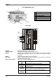
5 Technical Data General Frequency range Programmable radio channel Hamming distance Probability of non-recognition of error Typical working range Working temperature Time of reply to commands Time of reply to STOP Passive emergency time Number of avaible commands 902 - 928 MHz 32 ³8 < 10 exp-11 100 m -4°F - +158°F < 100 ms < 100 ms 1 second; (opt 0,35 second) 14+start+stop (+6 opt) Transmitting unit 9 - 30 Vac/dc (3W) Power supply external with 2,5 metres long cable Antenna meets FCC Part 15 for license-
KTC SYSTEM SERVICE MANUAL This manual is an integral part of the KTC system and aims to provide the main information required to substitute and programme the relevant parts. IT IS ESSENTIAL THAT YOU READ AND UNDERSTAND ALL OF THE MANUAL BEFORE YOU REPLACE OR PROGRAMME ANY PARTS OF THE KTC. It is also advisable to read and understand the "Installation and operation Manual". INDEX Page A B C GENERAL REMARKS Exploded view of the unit and spare parts A.1 Diagnostic flow chart A.
A.1 Exploded view of the unit and spare parts Exploded view of the transmitting unit TY P .... .... ........ DULE E...... ........ EE........ O MO NG LY. RADIEQ. RA SUPPN DEGR FR WER TIO PO OTEC PR AL R SERI BE NUM TRA 1A D T0 D EL MO 1 a TXEU Z 6U TQ l D at ......E16 90 MH c 7W20 E E1 ni ca ............0÷4304.7Vac/d.... .IP .05 ÷3 ........ Te ch ............ ...433 .10 .... NSM IT T ER . ert ura a. di ap so . ure zz g. d’u ca so nin di sic e in nu ale ope rm e il ma no taz ion a l . fore et .
LIKTCNA0 Page 17 Antenna (see page 7) F0ANTE00E34A0 Receiving case and base (see B.5) F0BASE00E54A0 Receiving case and base extension (see B.5) F0ESBA00E34A0 Receiving case (see B.5) R0CASS01P01A0 Receiving module (see B.3) R0RXDE06E08A0 Programming interface card (see B.4) F0CHAB02E07A0 Receiving case extension (see B.5) R0CASS01P01A0 Address key (see B.6) F0CHAB00E14D0 EL TY L RIA SE MBER NU RE CE IV E R 676 57 Ø5 PØ P RGØ1 AØTA 16A CA D 1 EU MO MHZ 16RX a ta RQ 790 dc 7W 0 l D ...........
A.2 Diagnostic flow chart In the event that the system or the machine activated by the Kit Transmission Commands doesn't function properly carry out the following procedure: Check the transmitting unit. Is the POWER signal on? NO Is the power supply terminal block connected correctly? NO Correctly connect the power supply to the terminal connector. NO Power the transmitting unit correctly YES Is the power supply with the correct parameters? YES YES No voltage.
Check the receiving unit. Is the POWER signal on? NO Is the power supply terminal block connected correctly? NO Correctly connect the power supply to the terminal connector. YES Is the power supply with the correct parameters? NO Power the receiving unit correctly YES No voltage. Is the fuse F1 burnt? YES NO Replace F1 YES Change the receiving case and base NO Is the ENABLE signal on? YES No voltage.
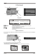
B.1 Opening and closing the unit Opening Closing Remove the antenna cable from the connector. Insert the antenna cable in the connector. Remove the cable and power connectors. Insert the power and cable connectors Opening Cut the strip which locks the unit with pliers. Open the cover and carry out the necessary operations. Page 20 Closing Lock the cover by inserting a strip in the hole provided. Close the cover.
B.2 Replacement of the transmitting module and/ or interface card Disassembly Assembly Carry out the opening described in procedure B.1. Carry out the closure described in procedure B.1. Extract the transmitting module interface card sandwich. Insert the transmitting module interface card in the appropriate fissure so that it fits correctly into the connector. Extract the antenna cable from the transmitting module.
B.3 Replacement of the receiving module Disassembly Assembly Carry out the opening described in procedure B.1. Carry out the closure described in procedure B.1. Extract the receiving module from the receiving unit. Put the receiving module in the appropriate fissure so that it fits correctly into the connector. Replace the receiving module. If you replace the transmitting module you have to: - remove the address key from the module to be substituted and put it in the new one (see procedure B.
B.5 Replacement of the case or/and base Disassembly Assembly Carry out the opening described in procedure B.1. Carry out the closure described in procedure B.1. Remove the module and the card from the unit to be replaced (see relevant replacement). Insert the modules and cards removed from the old unit, in the replacement unit. Replacement of the case and base Replacement of the only case With the help of a screwdriver move the two catches on the bottom of the case, as shown in the figure.
B.6 Replacement of the address key IN THE EVENT THAT ONE ADDRESS KEY DOES NOT FUNCTION, BOTH HAVE TO BE REPLACED (ONE IS TO BE FOUND ON THE TRANSMITTING MODULE AND ONE ON THE RECEIVING MODULE) Disassembly Assembly Carry out the disassembly described in the procedures B.2 and B.3. Carry out the assembly described in procedures B.2 and B.3. Unscrew the screws and remove both the address keys from the modules. Place the address keys in the appropriate modules fix the screws.
B.7 Replacement of the transmitting unit fuse Disassembly Assembly After removing the cable connectors, use a screwdriver to remove the cover to the bottom right of the transmitting unit. Close the cover to the bottom right and insert the cable connectors. Remove the fuse. Put in a new fuse. The replacement fuse has to have the indicated technical characteristics: B.8 Fuse Function FUSE POWER SUPPLY Technical characteristics 0.
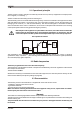
C Programming There are eight dip switches for programming in the transmitting and receiving modules. Operational functions and working frequencies may be programmed. The group of eight dip switches found in the module is necessary for programming some operations (see C.1)and setting the operating frequency (see C.2). The other group of four dip switches must be set as indicated in C.1. Group of 4 dip switches Group of 8 dip switches The dip switches must be programmed by qualified personnel.
C.1 Programming functions The dip switches 1 and 2 programme the same functions in 433 MHZ and in 870 MHZ modules. DIP SWITCH ON OFF 1 2 3 4 5 6 7 8 Group of 8 dip switches in the transmitting module E16STXEU_ ON OFF 1 2 3 4 5 6 7 8 ON OFF 1 2 3 4 5 6 7 8 ON OFF Functional description Dip switch 1 OFF enables the automatic off switch: if the transmitting unit is on but none of the commands is operational, after about 3,5 minutes the unit switches itself off automatically.
C.2 Programming the operational frequency A kit Transmission Commands has two operational modes: - manual frequency (programming with DIP8=ON) - automatic scan (programming with DIP 3- DIP 8= OFF). AUTEC PROGRAMMES THE OPERATIONAL MODE TO MANUAL FREQUENCY. MANUAL SELECTION: DIP 8 = ON In this mode the working frequency can be set using the dip switches set out in the tables below.
Via Pomaroli, 65 36030 Caldogno (VI) ITALY Tel : ++39 - 0444/901000 r.a. Fax: ++39 - 0444/901011 email: info@autec.it http://www.autec.