
User's Manual

Page 4 of 16 2 - Introduction LIMJNMA0
English
INSTRUCTIONS FOR DOCUMENT MANAGEMENT
The following minimum documentation is supplied with each radio remote control:
- transmitting unit manual
- receiving unit manual
- battery charger manual
- a guarantee certificate
- the radio remote control technical data sheet.
Make sure that the following documents have been supplied: if they are not, re-
quest them from Autec. Please specify the radio remote control serial number.
CERTIFICATE OF GUARANTEE
The conditions of the radio remote control guarantee are given in the “Certificate of
Guarantee”.
TECHNICAL DATA SHEET
The technical data sheet shows the wiring system between the receiving unit and
the machine. It should be compiled and checked by the installer, who has the re-
sponsibility of correct wiring. Once all necessary checks have taken place the in-
staller must sign the technical data sheet, which must be kept with the user's
manual (always keep a copy of this data sheet in case it is needed for administra-
tive purposes).
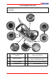
IDENTIFICATION PLATES
The radio remote control identification and approval data is given on plates that are
on both the transmitting unit and the receiving unit.
The plates MUST NOT be removed from where they are placed or damaged oth-
erwise the warranty will be forfeited.
MODULAR SERIES TECHNICAL DATA
Frequency band ................................................................................. 902 - 928 MHz
Programmable radio channel .................................................................................. 32
Hamming distance................................................................................................... ≥8
Probability of non-recognition of error ...................................................... <10 exp-11
Typical working range ....................................................................................... 100 m
Time of reply to commands ......................................................................... < 100 ms
Time of reply to STOP................................................................................. < 100 ms
Passive emergency time ........................................................................ * 0,35/1 sec.
* refer to paragraph “Programming” in the receiving unit manual, DIP nr. 1 settings.
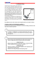
Following from the status of dip switch no.1 or possibly due to a fai-
lure (of the dip switch itself), a delay up to max 1 second may occa-
sionally occur between command release and actual deactivation of
outputs. This is due to the characteristics of radio propagation (i.e.:
EM interferences, near out-of-range condition). Care must be taken
to ensure that this could never lead to.
!