Transmitter System USER’S MANUAL Modular Series
Follow the indications and warnings given by the machine producer regarding the machine controlled by the radio remote control. The information contained in this manual considers a representative configuration of the radio remote control: please find radio remote control real configuration in the technical data sheet (attached to the manual). If this manual is lost or damaged, ask for a copy from AUTEC. Please specify the serial number of the relative radio remote control.
LIMKPNA0 1 INDEX AND CONVENTIONS INDEX Page 1 Index and Conventions 1 2 Introduction to Modular series 2 3 MK10, MK12 transmitting unit 5 4 Warnings for use 8 5 Warnings for maintenance 9 6 MK10, MK12 operation transmitting unit 10 7 Frequencies 12 8 Programming 13 9 MK10, MK12 transmitting unit diagnostic 14 CONVENTIONS In this manual, all important information is indicated using the following symbols and conventions: ! abcd. . . : WARNINGS abcd. . . : INSTRUCTIONS abcd. . .
LIMKPNA0 2 INTRODUCTION TO MODULAR SERIES Industrial radio remote controls of the Modular series are used to command machines from a distance. Each industrial radio remote control is made up of a portable transmitting unit, from which the user can remotely control the machine, and a receiving unit installed on board the machine itself. The transmitting unit uses radio frequencies to transmit a coded message which contains a value called address.
LIMKPNA0 Alll machines must undergo a risk analysis; therefore it is necessary to evaluate, within the limits of this analysis, if the machine can be radio remote controlled. The machine producer and/or the person who decides upon radio remote control use and installation is responsible for this analysis. Autec cannot be held responsible if the risk analysis is not carried out correctly.
LIMKPNA0 INSTRUCTIONS FOR DOCUMENT MANAGEMENT The following minimum documentation is supplied with each radio remote control: - transmitting unit manual - receiving unit manual - battery charger manual - a guarantee certificate - the radio remote control technical data sheet. Make sure that the following documents have been supplied: if they are not, request them from Autec. Please specify the radio remote control serial number.
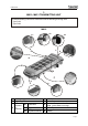
LIMKPNA0 3 MK10, MK12 TRANSMITTING UNIT These transmitting units can be used with one of the following receiving units: - Type R102 - Type R202 MK10 C2 C1 C3 C C D B A E F H G A B starting keyswitch signalling LED C actuator (if present) D E C1 pushbutton F C2 toggle switch G STOP pushbutton actuators pushbutton technical data plate, identification plate (in the battery housing) START pushbutton C3 keyswitch selector H battery Page 5
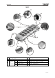
LIMKPNA0 MK12 C2 C3 C1 D C C B A E F H A B starting keyswitch signalling LED C actuator (if present) G D E C1 pushbutton F C2 toggle switch G STOP pushbutton actuators pushbutton technical data plate, identification plate (in the battery housing) START pushbutton C3 keyswitch selector H battery Page 6
LIMKPNA0 The transmitting units of Modular series are equipped with a redundant control that protects the “radio remote control + machine” system, when it is in neutral (rest position), from involuntary movements caused by possible radio remote control faults.
LIMKPNA0 4 WARNINGS FOR USE ! THE OPERATOR MUST ALWAYS VISUALLY FOLLOW all movements of the machine and its load remaining inside radio remote control typical working range. BE POSITIONED in a way that permits him to see the “machine + radio remote control” system, and above all the load, in the best possible way. Before using the radio remote control ALWAYS MAKE SURE that the STOP push-button can be pressed and released: if it does not work, do not use the radio remote control.
LIMKPNA0 5 WARNINGS FOR MAINTENANCE ! ENSURE THAT THE BATTERY HAS BEEN REMOVED FROM THE TRANSMITTING UNIT BEFORE CARRYING OUT ANY MAINTENANCE WORK. Any faults should be repaired by authorised Autec personnel using original Autec spare parts only.
LIMKPNA0 6 MK10, MK12 OPERATION TRANSMITTING UNIT POWER AND STARTING 1 To switch on the transmitting unit, insert the starting key and turn it to "I". 2 To start the radio remote control functions, press the “START” button for 1÷2 seconds. After starting, the green signalling LED always lights up. COMMAND ACTIVATION Operate the actuators and/or the selectors relevant to whatever movement or selection command is to be carried out.
LIMKPNA0 SWITCHING OFF The transmitting unit should be switched off each time work is stopped by turning the ignition key to "O" and extracting it (always put the key in a safe place). The unit may also switch off if the battery is not sufficiently charged and/or when the radio remote control is not used for more than 3,5 minutes (set DIP nr. 1: refer to paragraph 8 "Programming").
LIMKPNA0 7 FREQUENCIES The radio frequency of AUTEC radio remote controls is included in the group of frequencies permitted by regulations that are current at the moment of radio remote control entry onto the market. Each radio remote control is programmed by the producer in the AUTOMATIC scan mode (producer's standard programming) or MANUAL selection mode.
LIMKPNA0 8 PROGRAMMING ! The dip switches must be programmed with the battery removed from the transmitting unit and can be done only by authorised personnel. DIP SWITCHES ON E16STXUS1 RADIO TRANSMITTING MODULE Group of 4 dip switches The group of eight dip switches found in the module is necessary for programming some operations and setting the operating frequency. The programming set in the other group of four dip switches must never be modified.
LIMKPNA0 9 MK10, MK12 TRANSMITTING UNIT DIAGNOSTICS If the “machine+radio remote control” system does not start, check if the problem is caused by the radio remote control or the machine. Before carrying out any verifications, check the functioning of the machine with the cable control panel: - if it does not switch on, the problem lies with the machine itself - if it does switch on, the problem lies with the radio remote control.
Appendix: FREQUENCY TABLE E16STXUS1 MHz DIP SWITCH DIP SWITCH MHz 3 4 5 6 7 8 3 4 5 6 7 8 902.150 903.050 915.350 916.250 ON OFF OFF OFF OFF ON OFF OFF OFF ON OFF ON 903.850 OFF OFF OFF OFF ON ON 917.050 ON OFF OFF OFF ON ON 904.650 OFF OFF OFF ON ON ON 917.850 ON OFF OFF ON ON ON 905.525 OFF ON OFF OFF OFF ON ON ON OFF OFF OFF ON 906.325 OFF ON OFF ON OFF ON 918.675 919.525 ON ON OFF ON OFF ON 907.175 OFF ON OFF OFF ON ON ON OFF OFF ON ON 907.975 OFF ON OFF ON 920.
Via Pomaroli, 65 36030 Caldogno (VI) ITALY Tel : ++39 - 0444/901000 r.a. Fax: ++39 - 0444/901011 email: info@autec.it http://www.autec.