Original instructions Instruction Manual for the use and the maintenance of the Radio Remote Control AIR SERIES Part C: SIDEKICK SK4 Transmitting Unit AUTEC SRL Via Pomaroli, 65 36030 Caldogno (VI), ITALY Phone: +39 0444 901000 Fax: +39 0444 901011 Email: info@autecsafety.com www.autecsafety.
WARNING THIS PART OF THE MANUAL CONSISTS OF: Part C - Information, instructions and warnings for the SK4 Transmitting Unit. The Manual consists of Part A – General, Part B – Conformity and Frequencies, Part C – Transmitting Unit, Part D – Receiving Unit and Part E – Battery and Battery Charger, plus the Technical Data Sheet.
IT IS THE RESPONSIBILITY OF THE OWNER AND FACILITY OPERATOR, AND THEIR DESIGN PROFESSIONALS, that the installation, maintenance and operation of the Autec Radio Remote Control and all of its components are done solely and completely in accordance with this Manual, and with all applicable Laws, Regulations and Standards, even local.
IT IS THE RESPONSIBILITY OF THE OWNER AND FACILITY OPERATOR, AND THEIR OFFICERS, MANAGERS AND SUPERVISORS, to be certain that the areas in which the Machine operated by or through the Autec Radio Remote Control is located and operate are clearly delineated and marked in accordance with all Autec warnings and instructions, and all applicable Laws, Regulations and Standards, even local, and otherwise sufficient to alert and warn ALL PERSONS that the Machine is operated by or through a Radio Remote Control, an
INDEX 1 2 3 4 5 6 7 8 9 10 11 12 Information on the use of instructions ................................................................. 7 1.1 Structure of the Instruction Manual ................................................................. 7 1.2 Caption and terminology ................................................................................. 9 1.3 Symbols ......................................................................................................... 9 1.
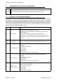
Information on the use of instructions 1 7 Information on the use of instructions Before reading this part of the Manual, you must read and understand the general part (Part A) of the Manual provided with the Radio Remote Control. 1.
Information on the use of instructions Usage and maintenance instructions are supplemented by the Radio Remote Control's Technical Data Sheet, that: -- describes the Transmitting Unit's configuration, -- indicates the relation between commands sent by the Transmitting Unit and those available on the Receiving Unit.
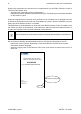
Information on the use of instructions 1.2 9 Caption and terminology Contact Autec if any of the instructions, symbols, warnings or images are not clear and understandable, or if you have doubts or questions.
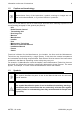
1.4 Information on the use of instructions To whom the instructions are addressed Addressees of instructions are listed in the paragraph with the same title in the general part: please refer to that part. 1.5 Instruction storage Regulation for the storage of instructions are described in the paragraph with the same title in the general part: please refer to that part. 1.
Brief product presentation 2 Brief product presentation 2.1 Series, Radio Remote Control and Unit 11 The object of this part of the Manual is the SK4 Transmitting Unit of a Air series' Radio Remote Control. Autec Air series' Radio Remote Controls are designed to be used on Machines and provide a command interface to their command and control system, to be used from an appropriate distance and position. 2.
3 Description of the Transmitting Unit Description of the Transmitting Unit A B C J H D S/N: XXXXXXX S/N: XXXXXXX MANUF. DATE XXXX TU ID: XXXXXXX TU ID: XXXXXXX MANUF.
Technical data 4 13 Technical data Power supply (battery AIRBM3V7L) ........................................................................ 3.7V Antenna ................................................................................................................... internal Housing material ........................................................................................... PA 6 (20%fg) Protection degree ........................................................................................
Plates 6 Plates The following instructions refer to the plates on different types of Radio Remote Controls where the SK4 Transmitting Unit may be used. 6.
Plates 6.
7 Light signals Light signals C BA C DE A Red LED B Green LED C LEDs for "Data Feedback" function D Green CHARGE LED E Red CHARGE LED The SK4 Transmitting Unit always has a green LED [B] and a red LED [A] that provide information regarding the Radio Remote Control. Symbol Meaning This symbol identifies the red LED [A]. This symbol identifies the green LED [B].
Light signals 17 Signal The green LED [B] is off. The green LED [B] is lit with a steady light. The green LED [B] repeats the sequence: two blinks and a pause. Meaning The Transmitting Unit is off. The Transmitting and Receiving Unit do not communicate. The working range of the remote control has been exceeded for more than 20 seconds. The green LED [B] repeats the sequence: three blinks and a pause. The Receiving Unit does not communicate with the transmitting Unit.
Light signals Signal The green [B] and red [A] LEDs are steady on during start up. The green [B] and red [A] LEDs blink 3 times per second during start up. The green LED [B] is lit with a steady light and the red LED [A] blinks two times per second during start up. Meaning A wrong "ID internal tx memory" has been inserted in the Transmitting Unit, or this is a "BACK-UP UNIT". "ID internal tx memory" is damaged. The START actuator is activated. The green [B] and red [A] LEDs blink alternating.
General operating instructions 8 General operating instructions 8.1 START pushbutton/selector 19 The START pushbutton/selector is used to: -- start the Radio Remote Control (see paragraph 8.5), -- activate the horn when the Radio Remote Control is started. 8.2 STOP pushbutton When the STOP pushbutton is activated, the Machine stops and the Transmitting Unit switches off.
General operating instructions 8.3.1 Indication of the SK4 Unit's battery charge level Perform the following procedure to check the SK4 Unit's battery charge level: 1. switch off the Transmitting Unit and unlock the STOP pushbutton, 2. activate command S1 (check in the Technical Data Sheet which actuator it corresponds to) and enable START until LED 1, LED 2 and LED 3 (indicating the battery charge level) illuminate: -- 1 LED on: low level -- 2 LEDs on: medium level. -- 3 LEDs on: maximum level.
General operating instructions 8.5 21 Starting up the Radio Remote Control Starting up the Radio Remote Control consists in establishing a radio link between the Transmitting Unit and the Receiving Unit. The Radio Remote Control start up is protected by a PIN code to prevent unauthorised use of the Machine. To activate the Radio Remote Control, enter the PIN code following the procedure described in paragraph 8.5.1.
General operating instructions 8.5.2 Procedure to modify the PIN code The Transmitting Unit activates only when the PIN code is entered. The PIN code can be modified to limit the use of the Radio Remote Control. To modify the PIN code, perform the following procedure with the Transmitting Unit switched off and the STOP pushbutton released. 1. Enable S0 and START and keep them enabled until the green LED blinks (1 blink per second). 2. Activate commands belonging to the PIN code in sequence. 3.
General operating instructions 23 Autec sets the G-Sense function so that when the sensor activates, one of the following situations occurs: -- the Transmitting Unit switches off, -- all the Radio Remote Control's commands are deactivated, except one particular Machine function, which is activated at the same time (e.g. horn). The Machine Manufacturer and/or the Installer have the responsibility to decide the behaviour of the G-Sense function.
8.8 General operating instructions Using the Transmitting Unit while recharging The SK4 Unit may or may not be enabled to control the Machine while the Unit itself is being charged. This activation depends on the "Charger Plug Enable" setting. Autec sets this function only upon request by the Installer and under his own responsibility. Check the Technical Data Sheet to know if this setting is enabled. 8.8.
General operating instructions 8.9 25 Radio link interruption When the radio link is incorrect or interrupted, the automatic stop function activates (see paragraph "Control devices" in the Instruction Manual's general part). The green LED on the Transmitting Unit switches from blinking slowly to blinking fast , steady on, repeats the sequence: two blinks and a pause or three blinks and a pause (see chapter 11). 8.
8.11 General operating instructions Switching off the Transmitting Unit Switch off the Transmitting Unit when not actively using the Radio Remote Control to operate the Machine, or when work is otherwise interrupted, even for short periods. Do not leave the Machine in dangerous conditions (even when recharging the Unit). FAILURE TO DO SO CAN RESULT IN SERIOUS BODILY INJURY OR DEATH AND/OR PROPERTY DAMAGE. An intentional switch off of SK4 Transmitting Unit occurs after pressing the STOP pushbutton.
General operating instructions 8.13 27 BACK-UP UNIT If the Transmitting Unit cannot be used, it can be replaced with a Transmitting Unit called "BACK-UP UNIT"; you need to ask for it to Autec. It is identical to the Unit that cannot be used any more; the only difference is the presence of the plate “BACK-UP UNIT” on the Transmitting Unit.
9 Instructions for the User Instructions for the User The chapter "Instructions for the User" in "Part A" of the Instruction Manual contains the warnings for the use that add to those provided in this chapter. Therefore, please refer to that part of the Manual.
Instructions for the User 29 -- adopt the necessary caution to avoid that the Machine operation causes dangerous situations of any type; to this end, the User's physical and health status shall be taken into account too; -- avoid leaving the Transmitting Unit unattended or in such a condition that it may be damaged, tampered with, operated by people who are not qualified or by the movement of people and/or objects (by way of example due to: fall, movement, contact); -- operate the Transmitting Unit by hol
Instructions for the User 3 4 5 6 7 LIUSK4N00_eng-00 AUTEC - Air series
Instructions for the User 31 The User must wear the Radio Remote Control with the belt as shown in the photo below, to avoid its fall, loss, loss of control, accidental contact and improper use. If the Transmitting Unit and the belt are used in a different way from the one described in the above mentioned figure, this results in improper use and may lead to damage to the Transmitting Unit, to the User, to people and/or property. Replace the belt or harness if it is damaged or worn.
Maintenance 10 Maintenance Instructions for correct Radio Remote Control maintenance are described in the chapter "Maintenance" included in "Part A" of the Instruction Manual. Therefore, please refer to that part of the Manual. 11 Malfunction signalled by the Transmitting Unit The table below lists malfunctions that are signalled by LEDs on the Transmitting Unit while it is not being charged, and the solution to those malfunctions.
Maintenance 33 Signals Possible reason The red LED blinks twice per second during start up. At least one of the pushbuttons is pressed or damaged. Bring the pushbuttons to the rest position. The red LED blinks three times per second during start up. The Unit is discharged. Recharge the Unit. The red LED is steady on for two seconds. The Transmitting Unit does not work correctly. Contact the support service. A wrong "ID internal tx memory" has been inserted in the Transmitting Unit.
12 Decommissioning and disposal Decommissioning and disposal Instructions for correct decommissioning and disposal of Radio Remote Controls are described in chapter "Decommissioning and disposal" in "Part A" of the Instruction Manual. Therefore, please refer to that part of the Manual.