
User's Manual


AUTEC - Air series
Installation 31
LIUAIR001_eng-00
Suppressors connected in parallel with contacts of commands' relays may
result conicting with the connection to a high-impedance load (by way of
example: some PLCs); please contact Autec to perform correct installation.
Loads connected to the relay outputs must ensure the minimum power,
voltage and current value that the contacts can switch (minimum values
are provided in the Installation Manual). Connect an additional load to the
outputs if necessary.
If a Receiving Unit's output (be it a solid state output or the contact of a relay)
is connected to a DC inductive load (by way of example: solenoid valves,
relays), it is advisable to connect a freewheeling diode in anti-parallel with
the driven load, to reduce the eects of demagnetizing currents.
Outputs of solid state commands shall never be connected to a power supply
positive or negative pole. Such connection could damage the outputs.
A voltage in the range 12 to 24 V
must always be applied to the power
supply input of the solid state commands.
Common wire related to diodes of solid state commands must be connected
with the common of all the Machine's freewheeling diodes. If that is not
possible, connect it to the Receiving Unit's power supply negative.
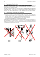
Group the wiring away from the radio module, in order to avoid interferences
and hazards related to electrical safety.
Evaluate the Radio Remote Control's wiring and remember that if the output
dedicated to the Machine's horn, siren or blinker is used for another command
due to application's and/or functional reasons, some procedures in the
“Conguration Menu” may result unavailable later on.
To wire the terminals corresponding to the commands' outputs, to the STOP
outputs and to the SAFETY outputs, it is recommended to use a slot screwdriver
with a tip size of 3.5x0.4mm.