
User's Manual


- 11 -
LIPROMA3-00
- 11 RI97-08PVZA module -
11
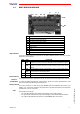
RI97-08PVZA MODULE
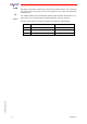
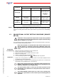
Dip switches
A group of 4 dip switches is present on the RI97-08PVZA module: they are used to
program some functions.
Data memory
The proportional output calibration values are stored in the removable data memory.
Restore
pushbutton To reset the initial proportional output values, press the restore pushbutton P until
the yellow LED stops blinking and remains on.
Rotary switch
The rotary switch S is used during the REMOTE SET UP calibration procedure (see
chapter 12): each of its positions corresponds to a specific parameter to be adjusted
(positions 6 to 9 are not used).
LED
Three LEDs are present:
- the red LED indicates the status and integrity of the data memory
- the green LED indicates the status and integrity of the RI97-08PVZA module
- the yellow LED indicates the status of the REMOTE SET UP function
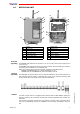
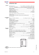
C1
connector for the proportional voltage-outputs
C2
connector for the proportional current-outputs (PWM)
C3
connector for the on/off inputs
C4
connector for the power supply
C5
connector for the connection to the bus board
D
dip switches
K1
data memory
L
LEDs
P
initial calibration restore pushbutton
S
rotary switch for calibration
C4 C1 C2
PS L
K1
D
C3
C5
DIP Pos.
FUNCTION
1
ON
the REMOTE SET UP function is active
(compulsory position during the calibration of the proportional output)
OFF
the REMOTE SET UP function is not active
(compulsory position during the normal functioning of the radio remote
control)
2
ON the transmitting unit has a speed selector with 2 or more speed levels
OFF
the transmitting unit has a speed selector that dynamically increases
and decreases the functioning speed
3/
do not modify the present programming
4/
not used