
User's Manual


4 Plates
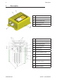
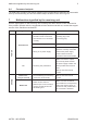
The receiving unit has the following plates:
Plate Position Content
radio remote control
identication plate
On the cover of the receiving unit
Radio remote control
serial number (SERIAL
N.), bar code and
manufacturing year.
technical data plate On the cover of the receiving unit
MODEL, TYPE and main
receiving unit technical
data, marking and
possible radio remote
control marks.
5 Light signals
The ENABLE LED blinks once every 5 seconds: the receiving and transmitting units are
not communicating.
The ENABLE LED blinks fast: the unit is ready to receive commands sent by the transmitting
unit.
The POWER LED is on: the receiving unit is powered on.
6 Operation
6.1 Electronic module
The electronic module contains the address key, where the radio remote control conguration
data are also stored. The receiving unit cannot work without this address key.
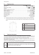
6.2 DIP switches
DIP switch 1 is used to set the frequency band.
DIP switch 2 shall always be set in the OFF position: do not modify it.
6.3 Internal light signals
The activation of each relay on the mother board is signalled by an LED near the relay.
4
LIRMCE00-00
Plates
AUTEC - AIR SERIES