
User's Manual


2 Technical data
Power supply ................................................................... 45-240V (max 40-264V 0.7A)
Fuse F1 ........................................................................................... 1.6A T 250V (5x20mm)
Digital inputs voltage ..................................................................... 10-60V (max 9-66V )
Antenna ............................................................................................... internal or dedicated
SAFETY contacts rated current ........................................................................ 4A (250V )
Fuses F2 and F3 ................................................................................ 4A T 250V (5x20mm)
STOP contacts rated current ............................................................................ 4A (250V )
Fuses F4 and F5 ................................................................................ 4A T 250V (5x20mm)
Commands rated current
a
................................................................................ 6A (250V )
b
Housing material .............................................................................................PA 6 (20%fg)
Protection degree ......................................................................................... IP65 (NEMA 4)
Dimensions ...............................................................................................185x235x105mm
Weight .............................................................................................................2.2kg (4.9Lb)
a. Command contacts' rated current for any optional card is provided in the technical data sheet.
b. The rated current may be up to 10A only if both terminals are used for each contact. If the radio
remote control has been wired by Autec, please refer to values provided in the technical data
sheet.
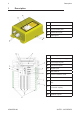
A 252.5 mm
B 148 mm
C 116 mm
D 253 mm
3 Technical data sheet
The technical data sheet contains the wiring diagram showing the connection between the
receiving unit and the machine. It also contains the transmitting unit conguration and shows
the matching between commands sent and machine functions/movements.
Each technical data sheet must be lled in, checked and signed by the installer, who is
responsible for a correct wiring.
A copy of the technical data sheet must always be kept together with this manual (always
keep a copy of this data sheet for administrative purposes).
The wiring of the receiving unit outputs must always reect the wiring
indicated in the technical data sheet.
AUTEC - AIR SERIES
Technical data 3
LIRMCE00-00