A0 L I BR0 0 D0 1 6 6 LIUAIR1AU3-01 Air series user manual
sa fe FS arch A itec fle x tu re
1 INDICE 1 Descrizione radiocomando serie AIR ......................................................................................... 1.1 Funzionamento del radiocomando .......................................................................................... 1.2 Applicazioni ............................................................................................................................. 1.3 Dati tecnici .........................................................................................
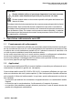
2 Descrizione radiocomando serie AIR Funzionamento del radiocomando LEGENDA Questo simbolo indica un’avvertenza importante la cui non osservanza porta a una situazione di pericolo per le persone e le cose. @ Questo simbolo indica un documento reperibile nella parte dedicata del sito internet di Autec. Ricordarsi che tutta la documentazione deve essere conservata per tutta la vita del radiocomando: dopo averla letta tenerla a disposizione per future consultazioni.
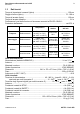
Descrizione radiocomando serie AIR 3 Dati tecnici 1.3 Dati tecnici Tempo di risposta dei comandi (tipico) ..................................................................... 100 ms Raggio d’azione (tipico) ....................................................................................... 75 - 100 m Tempo di arresto (tipico) .......................................................................................... 100 ms Tempo di arresto massimo ...................................................
4 Conformità e frequenze Funzione di sicurezza: protezione dell’arresto 1.4 Funzione di sicurezza: protezione dell’arresto La funzione di arresto porta la macchina in uno stato sicuro ogni volta che è necessario fermarla a causa di una situazione potenzialmente pericolosa.
Conformità e frequenze 5 Banda di frequenze 915-928 MHz 2.1.2 Frequenze Il collegamento radioelettrico tra le unità dei radiocomandi Autec della serie AIR avviene ad una delle frequenze ammesse dalle normative europee in vigore al momento dell’immissione nel mercato. Frequenze utilizzate nella banda di frequenza 433.050-434.790 MHz ............................. 64 Potenza RF ...............................................................................................................
6 Valutazione dei rischi Valutazione dei rischi per macchine radiocomandate 3 Valutazione dei rischi Occorre valutare sempre se la macchina può essere radiocomandata o meno. Infatti, come richiesto dalle normative tecniche del mercato in cui il sistema “macchina+radiocomando” viene impiegato, è necessario effettuare per ogni macchina una valutazione dei rischi con la relativa analisi. Solo l’esito positivo di questa valutazione può consentire l’installazione e l’utilizzo del radiocomando.
Valutazione dei rischi 7 Formazione del personale 3.1.3 Protezione dalle attivazioni involontarie L’involucro dell’unità trasmittente è realizzato in modo da proteggere gli attuatori da attivazioni involontarie, soddisfando le necessità lavorative, le richieste ergonomiche e i vincoli normativi. Si devono valutare ed eventualmente adottare misure di protezione aggiuntive per gli attuatori (es.
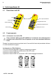
8 Unità trasmittente A8 Descrizione unità A8 4 Unità trasmittente A8 4.1 Descrizione unità A8 LED Vite e coperchio batteria Pulsante STOP Tasti comandi Targhetta dati tecnici Tasto FUNCTION Targhetta di identificazione Contatti per la carica Tasto START 4.2 Funzionamento 4.2.1 Avviamento con codice PIN Come richiesto dalla norma IEC 60204-32, l’avviamento del radiocomando è protetto da un codice PIN al fine di impedire un uso non autorizzato della macchina.
Unità trasmittente A8 9 Funzionamento Avviamento con PIN personalizzato Se richiesto dalla valutazione dei rischi, il PIN può essere modificato al fine di impedire un uso non autorizzato. La procedura per personalizzare il PIN è riportata nel documento “Menu of Transmitting Unit (MTU)” reperibile nella parte dedicata del sito internet di Autec.
10 Unità trasmittente A8 Avvertenze per l’utilizzo 4.2.4 Tasto FUNCTION Al tasto FUNCTION possono essere associate differenti funzioni dei relè nel ricevitore (vedere scheda tecnica). 4.2.5 STOP Il pulsante STOP va premuto solo quando c’è la necessità di arrestare immediatamente la macchina per il verificarsi di una qualunque situazione di pericolo. La pressione del pulsante STOP, oltre ad arrestare la macchina, spegne l’unità trasmittente.
Unità trasmittente A8 11 Avvertenze per l’utilizzo - non avviare o azionare mai l’unità trasmittente in posti chiusi, fuori visibilità o fuori dal raggio d’azione del radiocomando: anche in questi casi è infatti possibile creare un collegamento radioelettrico con il rischio di far eseguire dei comandi non voluti alla macchina radiocomandata - apprendere la corrispondenza tra i tasti e le manovre della macchina indicata nella scheda tecnica allegata e la simbologia presente nel pannello dell’unità A8 (la
12 Unità trasmittente A8 Carica dell’unità A8 4.4 Carica dell’unità A8 All’interno dell’unità A8 è presente una batteria ricaricabile (AIRBM3V7L) che viene fornita parzialmente caricata. Per utilizzare correttamente l’unità A8 e la sua batteria è necessario conoscere e tenere in considerazione quanto indicato nel capitolo relativo.
Unità ricevente 13 Descrizione unità ricevente G 5 Unità ricevente Targhetta dati tecnici Targhetta identificazione LED ENABLE LED POWER 5.1 Pressacavo Descrizione unità ricevente G Uscite comandi F1: fusibile per l’alimentazione Connettore per l’alimentazione Ingressi digitali Fusibili del circuito di SAFETY Modulo elettronico Fusibili del circuito di STOP Uscite SAFETY Uscite STOP DIP switch Segnalazioni luminose interne Fusibile F1 .........................................................
14 Unità ricevente Descrizione unità ricevente L 5.2 Descrizione unità ricevente L Segnalazioni luminose interne Fusibile per l’alimentazione Connettore per l’alimentazione Fusibili del circuito di SAFETY Modulo elettronico Fusibili del circuito di STOP Uscite SAFETY Uscite STOP DIP switch Uscite comandi Fusibile F1 .................................................................................... 1.6 A T 250 V (5x20 mm) Fusibile F2 e F3..........................................................
Unità ricevente 15 Avvertenze per l’installazione 5.3.4 Segnalazioni luminose interne L’attivazione di ciascun relè presente sulla scheda base è segnalata da un LED nei pressi del relè stesso. 5.3.5 Uscite comandi La corrispondenza fra comando inviato dall’unità trasmittente e uscita attivata nell’unità ricevente è indicata nella scheda tecnica. 5.
16 Unità ricevente Avvertenze per l’installazione 5.4.3 Posizionamento dell’antenna L'antenna si trova all'interno dell'unità ricevente. Pertanto, installare l’unità ricevente in modo che schermi, strutture o materiali non ostacolino il collegamento radioelettrico; in particolare: - l’unità ricevente non deve essere all’interno di contenitori metallici chiusi - l’unità ricevente deve essere collocata ad almeno 50 cm da oggetti metallici circostanti.
Batteria AIRBM3V7L 17 Avvertenze per l’installazione 5.4.5 Al termine dell’installazione Verificare che nel corso dell’installazione non siano state eseguite operazioni che rendano inefficaci i meccanismi di sicurezza previsti sul radiocomando e/o presenti all’interno della macchina. Verificare che sia impostata la banda di frequenze permessa nel Paese di utilizzo del radiocomando (vedere capitolo 2).
18 Batteria AIRBM3V7L Dati tecnici Usare esclusivamente batterie originali Autec e caricare la batteria solo con alimentatori forniti da Autec per questa unità. L'uso improprio di una batteria e di un alimentatore può comportare il pericolo di incendio, deflagrazione o altri pericoli. L'uso di batterie diverse da AIRBM3V7L fa decadere qualsiasi garanzia. Non utilizzare mai batterie che risultino danneggiate.
Docking station 19 Rottamazione 6.3 Rottamazione Riciclare le batterie applicando le disposizioni locali: nell’Unione Europea sono previsti modi distinti per la raccolta e il riciclaggio di batterie in conformità alla Direttiva 2006/66/CE e successive modifiche. Non gettare le batterie assieme ai rifiuti domestici o nel fuoco in quanto potrebbero esplodere.
20 Docking station Collegamento tra docking station e alimentatore 7.1 Collegamento tra docking station e alimentatore Per collegare la docking station all’alimentatore è necessario inserire lo spinotto dell’alimentatore nella presa della docking station. L’alimentatore deve essere alimentato da una presa facilmente raggiungibile e scollegabile. Spinotto 7.1.
Manutenzione del radiocomando 21 Manutenzione ordinaria 8 Manutenzione del radiocomando Le istruzioni che seguono forniscono le informazioni per eseguire in sicurezza le operazioni di manutenzione ordinaria e straordinaria del radiocomando.
22 Manutenzione del radiocomando Manutenzione ordinaria 8.1.
Manutenzione del radiocomando 23 Manutenzione straordinaria 8.2 Manutenzione straordinaria La manutenzione straordinaria è l'operazione o l'insieme delle operazioni di riparazione rese necessarie da guasti, rotture o malfunzionamenti del radiocomando, che hanno lo scopo di ripristinare le condizioni d'uso e di funzionamento originarie.
24 Manutenzione del radiocomando Malfunzionamenti 8.3.1 Segnalazioni dell’unità trasmittente Nel caso in cui il problema persista dopo avere attuato la soluzione di seguito indicata, contattare il servizio di assistenza. Rosso Verde LED Segnalazioni Soluzioni Acceso fisso Avviare il radiocomando. L’unità trasmittente e riceven- Se il radiocomando non si avvia verificare che l’unità ricevente sia te non comunicano tra loro. alimentata.
Manutenzione della macchina 25 Malfunzionamenti 8.3.2 Segnalazioni dell’unità ricevente Nel caso in cui il problema persista dopo avere attuato la soluzione di seguito indicata, contattare il servizio di assistenza. LED Segnalazioni Possibile causa Soluzioni La spina di collegamento tra radiocomando e macchina Agganciare correttamente la spinon è connessa correttamen- na di collegamento. te. Il fusibile F1 è guasto. ENABLE POWER Spento Sostituire il fusibile.
26 Rottamazione Malfunzionamenti AUTEC - Serie AIR
27 INDEX 1 Description of the AIR series' radio remote controls .............................................................. 1.1 How the radio remote control works ..................................................................................... 1.2 Applications ........................................................................................................................... 1.3 Technical data ...................................................................................................
28 Description of the AIR series' radio remote controls How the radio remote control works CAPTION This symbol indicates an important warning that, if disregarded, leads to a hazardous situation for people and property. @ This symbol indicates a document that can be found in the specific section on Autec's website. The documentation must be kept for the whole life of the radio remote control: after reading it, keep it on hand for future reference.
Description of the AIR series' radio remote controls 29 Technical data 1.3 Technical data Command response time (typical) ............................................................................. 100 ms Working range (typical) .........................................................................................75 - 100 m Stop time (typical) ..................................................................................................... 100 ms Max. stop response time .......................
30 Conformity and frequencies Safety function: stop protection 1.4 Safety function: stop protection The stop function brings the machine to a safe state every time it is necessary to stop it due to a potentially hazardous situation. Depending on the situation, this function can either be deliberately activated by the operator through the STOP pushbutton, or it is automatically activated when the radio link is incorrect or interrupted (the receiving unit autonomously stops the radio remote control). 1.
Conformity and frequencies 31 Frequency band 915-928 MHz 2.1.2 Frequencies The radio link between the units of Autec AIR series radio remote controls is built at one of the frequencies permitted by the European standards in force when the system is put on the market. Frequencies used in the frequency band 433.050-434.790 MHz ..................................... 64 RF power...................................................................................................................
32 Risk assessment Risk assessment for radio remote controlled machines 3 Risk assessment Always evaluate whether the machine can be radio remote controlled. In fact, as required by technical standards specific to the market where the system “machine+radio remote control” is used, each machine must undergo risk assessment and risk analysis. The radio remote control can only be installed if this assessment gives positive results.
Risk assessment 33 Staff training Assessment shall be made to establish possible additional protection measures for the actuators (i.e. commands requiring two-hand operation, “dead-man” function) if particular environments, equipment and working modes could cause accidental bumps to the actuators. 3.
34 A8 transmitting unit Description of the A8 unit 4 A8 transmitting unit 4.1 Description of the A8 unit LEDs Screw and battery cover STOP pushbutton Command pushbuttons Technical data plate FUNCTION pushbutton Identification plate Contacts for recharge START pushbutton 4.2 Operation 4.2.1 Start up with PIN code As required by standard IEC 60204-32, the radio remote control start up is protected by a PIN code, in order to prevent non authorised use of the machine.
A8 transmitting unit 35 Operation Start up through customised PIN If the risk assessment requires this, the PIN code may be modified to prevent unauthorised use. The procedure to set a customised PIN is provided in the document “Menu of Transmitting Unit (MTU)”; you can find this document in the dedicated section on Autec's website.
36 A8 transmitting unit Warnings for use Signals from the other four LEDs depend on the function matching the FUNCTION pushbutton (or on digital inputs, if wired on the G receiving unit). 4.2.4 FUNCTION pushbutton The FUNCTION pushbutton can be matched with different relay functions on the receiver's side (see technical data sheet). 4.2.5 STOP The STOP pushbutton can only be pressed when it is necessary to immediately stop the machine when a dangerous condition occurs.
A8 transmitting unit 37 Warnings for use - only start up the transmitting unit when starting work: improper use may cause hazardous situations; - never start up or use the transmitting unit in closed spaces, with the machine not in sight, or outside the radio remote control working range: in such cases it is in fact still possible to build a radio link, thus causing the risk that unwanted commands be carried out by the machine; - get familiar with the correspondence between the pushbuttons and the machin
38 A8 transmitting unit Recharging the A8 unit 4.4 Recharging the A8 unit The A8 unit contains a rechargeable battery; the provided battery is partially charged. To correctly use the A8 unit and its battery, the related chapter shall be fully understood and kept into account. First power on the docking station with its power supply unit and then: 1) insert the A8 unit into the docking station: a steady on red 1b LED indicates that charging has started (max.
Receiving unit 39 Description of G type receiving unit 5 Receiving unit Technical data plate Identification plate ENABLE LED POWER LED 5.1 Cable gland Description of G type receiving unit Command outputs F1: power supply fuse Connector for power supply Digital inputs Fuses of SAFETY circuit Electronic module Fuses of STOP circuit SAFETY outputs STOP outputs DIP switches Internal light signals Fuse F1 ......................................................................................... 1.
40 Receiving unit Description of type L receiving unit 5.2 Description of type L receiving unit Internal light signals Power supply fuse Connector for power supply Fuses of SAFETY circuit Electronic module Fuses of STOP circuit SAFETY outputs STOP outputs DIP switches Command outputs Fuse F1 ......................................................................................... 1.6 A T 250 V (5x20 mm) Fuses F2 and F3 .............................................................................
Receiving unit 41 Warnings for installation 5.3.4 Internal light signals The activation of each relay on the mother board is signalled by an LED near the relay. 5.3.5 Command outputs The data sheet contains information regarding the correspondence between the commands sent by the transmitting unit and the related output enabled in the receiving unit. 5.
42 Receiving unit Warnings for installation 5.4.3 Positioning the antenna The antenna is inside the receiving unit. Hence, install the receiving units so that shields, structures or materials do not obstruct the radio link; in particular: - the receiving unit shall not be placed inside closed metal containers - the receiving unit must be placed at least 50 cm far from metal objects in its surroundings. If this warning is disregarded, the radio remote control working range may be reduced. 5.4.
Battery AIRBM3V7L 43 Warnings for installation 5.4.5 At end of installation Make sure that during installation the safety mechanisms on the radio remote control and/or in the machine have not been made ineffective by possible procedures carried out. Make sure that the frequency band set in the radio remote control is permitted in the Country of use (see chapter 2).
44 Battery AIRBM3V7L Technical data Only use original Autec batteries and only recharge batteries with power supply units provided by Autec for this unit. Improper use of batteries and power supply units may pose the hazard of fire, explosion, or other hazards. Use of batteries other than AIRBM3V7L will void the warranty. Never use damaged batteries.
Docking station 45 Disposal 6.3 Disposal Apply local rules when disposing of batteries: in the European Union there are different collection and recycling schemes for batteries in compliance with the 2006/66/EC Directive and amendments . Do not throw the batteries away with domestic trash and do not burn them as they may explode.
46 Docking station Connecting the docking station and the power supply unit 7.1 Connecting the docking station and the power supply unit Insert the jack plug of the power supply unit in the corresponding socket on the docking station, in order to connect them. The power supply unit must be connected to a socket that can be easily reached and disconnected. Jack plug 7.1.1 Recharging To recharge the battery, make sure that the machine is in a safe state, so that it cannot generate hazards (i.e.
Radio remote control maintenance 47 Routine maintenance 8 Radio remote control maintenance The following instructions provide information to safely carry out routine and special maintenance operations for the radio remote control.
48 Radio remote control maintenance Routine maintenance 8.1.1 Daily routine maintenance Before starting to work: - make sure that the recharging contacts are always clean - make sure that the pushbuttons' gaskets are intact, soft and elastic - make sure that the transmitting unit panel symbols can be easily recognised and replace the panel if necessary - check that the three plates on the transmitting unit are readable and intact - make sure that the mechanical operation of the STOP pushbutton is correct.
Radio remote control maintenance 49 Special maintenance 8.2 Special maintenance Special maintenance consists of repairs needed due to radio remote control failure, damage or malfunction, carried out with the aim of restoring the original usage and working conditions.
50 Radio remote control maintenance Malfunctions 8.3.1 Signals on the transmitting unit If the problem persists after the suggested solution has been carried out, contact the support service. Green LEDs Signals Steady on Blinks fast The radio remote control is not Press the START pushbutton unstarted up. til the green LED blinks slowly. Blinks slowly (one blink per second) The radio remote control is See paragraph “Signals on the started up. receiving unit”.
Machine maintenance 51 Malfunctions 8.3.2 Signals on the receiving unit If the problem persists after the suggested solution has been carried out, contact the support service. LEDs Signals Possible reason Solutions The connecting plug between the radio remote control and Correctly plug in the connecting the machine is not connected plug. correctly. POWER Switched off On Fuse F1 is damaged. Replace the fuse. Wrong or no power supply.
AUTEC SRL via pomaroli, 65 - 36030 Caldogno - Italy - phone +39.0444.901000 - fax +39.0444.901011 - info@autecsafety.com - www.autecsafety.