
User's Manual


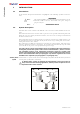
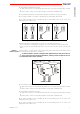
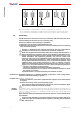
Table Of Contents
- Copertina esterna fronte LIMM&SA0-00.pdf
- Copertina interna fronte LIMM&SA0-00.pdf
- LIMM&SA0-00.pdf
- 1 Introduction
- 2 Transmitting units
- 3 Receiving unit
- 3.1 Description of the receiving unit
- 3.2 Inner parts of the “Master/Slave” receiving units
- 3.3 Inner parts of the “Master/Master” receiving units
- 3.4 General warnings for the installation of the receiving unit
- 3.5 Specific warnings for the installation of the receiving unit
- 3.6 Warnings for the maintenance of the receiving unit
- 3.7 External signal lights of the receiving unit
- 3.8 Internal signal lights of the receiving unit
- 4 Operating mode of “Master/Slave”
- 5 Operating mode of “Master/Master”
- 6 Operating mode of the transmitting units
- 7 Maintenance
- 8 Programming
- 9 Diagnostics
- bianca A4.pdf
- Copertina esterna retro LIMM&SA0-00.pdf

1 Introduction
- 6 -
LIMM&SA0-00.fm
Identification
plates
The radio remote control identification and approval data is given on plates that are on both the
transmitting unit and the receiving unit.
These plates MUST NOT be:
- removed from their position
- altered or damaged in any case.
1.6 Modular Series technical data
Due to the characteristics of radio propagation (i.e.: EM interferences, near out-
of-range condition), a delay up to one second may occasionally occur between
command release and actual deactivation of the corresponding output. Care
must be taken to ensure that this could never lead to a dangerous situation in the
specific uses.
1.7 Frequencies
The radio frequency of Autec radio remote controls is included in the group of frequen-
cies permitted by regulations that are current at the moment of radio remote control
entry onto the market.
The two transmitting units UTX-M and UTX-S and the two receiving units URX-1 and URX-2 op-
erate in manual selection mode: when operating in this mode it is possible to work at a specific
frequency that must be set manually by programming the dip switches in the radio modules (see
chapter 8).
Frequencies
for the
“Master/Slave”
Frequencies set in a “Master/Slave” system must undergo the following rules:
- the transmitting unit UTX-M and the transmitting unit UTX-S must work at two
different frequencies
- the receiving unit URX-1 must have the same working frequency as the trans-
mitting unit UTX-M
- both working frequencies of the receiving unit URX-2 must be set as explained
in paragraph 3.2.
Frequencies
for the “Master/
Master”
Frequencies set in a “Master/Master” system must undergo the following rules:
- the transmitting unit UTX-M and the transmitting unit UTX-S must work at two
different frequencies
- both working frequencies of the receiving unit URX-1 must be set as explained
in paragraph 3.3.
- both working frequencies of the receiving unit URX-2 must be set as explained
in paragraph 3.3.
Frequency band with radio module E16S_XEU1..................................... 902 - 928 MHz
Available radio channels ..................................................................................... 32
Hamming distance ............................................................................................ ≥ 8
Probability of undetected error................................................................ <10 exp-11
Typical working range ....................................................................... 330 ft [100 m]
Command response time .......................................................................... ~ 100 ms
STOP command response time
a
.................................................................. ~ 100 ms
Passive emergency time (or passive stop)
b
................................................ 0.35/1 sec.
Safety function category according to the EN 954 - 1
STOP protection............................................................................................. Cat. 3
a. valid when the radio link between transmitting and receiving unit is not disturbed.
b. depending on DIP nr. 1 settings, see paragraph 8.2.