
User's Manual
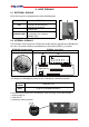
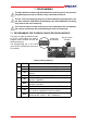
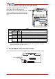


Table Of Contents

Page 10 6 - Light signals LI14CAA0-00 - AmEn.fm
6 LIGHT SIGNALS
6.1 EXTERNAL SIGNALS
Each receiving unit is equipped with a status indicating light:
SIGNAL TYPE MEANING
LIGHT SWITCHED
OFF
Receiving unit not powered
STEADY LIGHT
Receiving unit powered
(POWER ON)
BLINKING LIGHT
Radio link between the transmitting
and receiving unit is present
(ENABLE ON)
6.2 INTERNAL SIGNALS
The activation of each relay on the E16B14AC mother board is signalled by a LED (A) near
the relay. The same indication is repeated on the bus board (E16RI02_) if present.
E16B14AC mother board E16RI02_ bus board
A
S
T
O
P
/
E
N
A
S
A
F
E
T
Y
R
L
1
R
L
2
R
L
3
R
L
4
R
L
5
R
L
.
.
L
e
d
1
L
e
d
2
S
T
A
R
T
/
A
B
Data memory
Two diagnostic LEDs (B) are present on the E16RI02B bus board that indicate:
LED 1
(GREEN)
LED 2
(RED)
Three LEDs are present on the E16SRXUS1 radio receiving module that indicate:
1. power supply on
2. radio link on
3. frequency scanning search
123
diagnostic LED
code alarm in the data memory (see paragraph 7.3 "Program-
ming the E16RI02B bus board")