AC Receiver System USER’S MANUAL
AC Receiver System USER’S MANUAL
Follow the indications and warnings given by the machine producer regarding the machine controlled by the radio remote control. The information contained in this manual considers a representative configuration of the radio remote control: please find radio remote control real configuration in the technical data sheet (attached to the manual). If this manual is lost or damaged, ask for a copy from AUTEC. Please specify the serial number of the relative radio remote control.
1 INDEX AND CONVENTIONS 1.1 INDEX 1 1.1 1.2 2 2.1 2.2 2.3 3 3.1 4 5 5.1 5.2 5.3 6 6.1 6.2 7 7.1 7.2 7.3 8 Index and conventions .......................................................................................... 1 Index ........................................................................................................................ 1 Conventions ............................................................................................................. 1 Introduction ........................
2 INTRODUCTION 2.1 GENERAL DESCRIPTION Industrial radio remote controls are used to control machines from a distance. Each industrial radio remote control is made up of a portable transmitting unit, from which the user can remotely control the machine, and a receiving unit installed on board the machine itself. The transmitting unit uses radio frequencies to transmit a coded message which contains a value called address.
Autec cannot be held responsible if the radio remote control is installed on applications that are different from those permitted: PERMITTED USES Hoisting machines (construction cranes, bridge cranes, machines for material handling in general,…). FORBIDDEN USES Machines installed in areas where equipment with explosion-proof characteristics is required. Machines for moving, raising and transporting people.
Technical data sheet The technical data sheet shows the wiring diagram between the receiving unit and the machine. The technical data sheet must be filled in and checked by the installer, who is responsible for a correct wiring. Once all necessary checks have been carried out, the installer must undersign the technical data sheet, which must be kept with the user's manual (always keep a copy of this data sheet for administrative purposes).
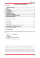
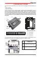
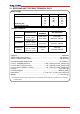
3 RECEIVING UNIT TYPE R402 The receiving units Type R402 can be used with the transmitting units of the following series: - LIGHT SERIES - MODULAR SERIES These receiving units are equipped with a safety function called SAFETY that protects the system “machine+radio remote control”, when it is in neutral (rest) position, from unintended movements caused by possible radio remote control faults.
3.1 RECEIVING UNIT TYPE R402 TECHNICAL DATA Power supply MIN. 18 25 36 70 50 Voltage (Vac) Frequency (Hz) Absorbed power (VA) NOM. 25 35 50 110 MAX.
4 WARNINGS FOR INSTALLATION Installation must only be carried out by qualified people and in accordance with installation country rules. The installer MUST ALWAYS respect the following warnings: PLACE the receiving unit vertically, with the cable gland (or plug) facing down. PLACE the receiving unit so that it is not completely shielded by metal parts and that it is easily reachable. FIX the receiving unit at least in four points, using the specific holes located in the housing.
5 WARNINGS FOR MAINTENANCE ALWAYS ENSURE THAT THE RECEIVING UNIT HAS BEEN DISCONNECTED FROM THE POWER SOURCE BEFORE CARRYING OUT ANY MAINTENANCE WORK. All control and maintenance actions carried out on the radio remote control must be verified and recorded by the person in charge of carrying out maintenance on the machine. Routine maintenance carried out as described in this manual is fundamental for using the radio remote control safely.
External electric conductors It is recommended every twelve months to: 1. verify integrity along the full length of the cable which connects the receiving unit to the machine 2. verify the integrity and the electrical connection of the plugs and the connection socket 3. check the strips or other fixing systems and replace them if necessary 4. make sure that the connecting cable is not deteriorated, especially the part near the cable holder. 5.
6 LIGHT SIGNALS 6.1 EXTERNAL SIGNALS Each receiving unit is equipped with a status indicating light: SIGNAL TYPE MEANING LIGHT SWITCHED Receiving unit not powered OFF Receiving unit powered (POWER ON) Radio link between the transmitting BLINKING LIGHT and receiving unit is present (ENABLE ON) STEADY LIGHT 6.2 INTERNAL SIGNALS The activation of each relay on the E16B14AC mother board is signalled by a LED (A) near the relay. The same indication is repeated on the bus board (E16RI02_) if present.
7 PROGRAMMING The dip switches must be programmed when the receiving unit is not powered. Programming must only be carried out by authorized personnel. For the correct functioning, the group of 8 dip switches (excluding DIP 1) for the radio modules E16STXUS1 (transmitting unit) and E16SRXUS1 (receiving unit) must be set in the same way. The incorrect closure of the receiving unit can compromise the seal between the casings and thereby the protection degree from dust and water. 7.
7.2 PROGRAMMING THE E16B14AC MOTHER BOARD Dip switch programming shall correspond to that given on the technical data sheet. Dip switches 4-5-6 of the DSW1 group are used to program some of the radio remote control functions as illustrated in the following table: DSW1 DSW1 PROG. P1 P2 P3 DIP SWITCH SEL. POS.
8 RECEIVING UNIT DIAGNOSTICS If the system “machine+radio remote control” does not start, check if the problem is caused by the radio remote control or the machine. Therefore, before carrying out any verification connect the cable control unit: if the machine does not start, the problem lies with the machine itself. If, on the other hand, the machine only starts using the cable control panel, the problem lies with the radio remote control.
Page 14 8 - Receiving unit diagnostics LI14CAA0-00 - AmEn.
Appendix: FREQUENCY TABLE E16SRXUS1 MHz DIP SWITCH DIP SWITCH MHz 3 4 5 6 7 8 3 4 5 6 7 8 902.150 903.050 915.350 916.250 ON OFF OFF OFF OFF ON OFF OFF OFF ON OFF ON 903.850 OFF OFF OFF OFF ON ON 917.050 ON OFF OFF OFF ON ON 904.650 OFF OFF OFF ON ON ON 917.850 ON OFF OFF ON ON ON 905.525 OFF ON OFF OFF OFF ON ON ON OFF OFF OFF ON 906.325 OFF ON OFF ON OFF ON 918.675 919.525 ON ON OFF ON OFF ON 907.175 OFF ON OFF OFF ON ON ON OFF OFF ON ON 907.975 OFF ON OFF ON 920.
Via Pomaroli, 65 36030 Caldogno (VI) ITALY Tel : ++39 - 0444/901000 r.a. Fax: ++39 - 0444/901011 email: info@autec.it http://www.autec.