
User's Manual
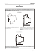
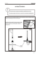
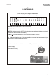
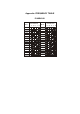

Table Of Contents

9
Page 15
LIE&LQA0
PROGRAMMING
!
The group of eight dip switches found in
the module permits the programming of
different operating mode and the setting
of operating frequency.
The programming set in the other group
of four dip switches must never be
modified.
!
These eight dip switches must be programmed in the same manner
as the group of 8 dip switches (excluding DIP 1) present in the radio
module of the transmitting unit (see manual).
DIP SWITCHES ON E16SRXUS1 RADIO RECEIVING MODULE
Group of 8 dip switches
Group of 4
dip switches
Group of 8
dip switches
(*) With the MK10, MK12, MJ transmitting unit the dip switch should be at ON.
(**) With the MK12 transmitting unit the dip switch should be at ON.
DIP POS.
DESCRIPTION
ON
Passive emergency at 0,35 second
1 (*)
OFF
Passive emergency at 1 second
ON
Deactivated of low battery warning from horn on machine
2 (**)
OFF
Activation of low battery warning from horn on machine
ON
With DIP 8 OFF automatic scan mode of the freque ncies
in the 915 - 928 MHz
3
OFF
With DIP 8 OFF automatic scan mode of the frequencies
in the 902 - 915 MHz
3 - 7 ON/OFF
With DIP 8 ON see “Appendix: Frequency Table”
ON
Manual selection of frequencies with
DIP 3 - DIP 7 (see “Appendix: Frequency Tab le”)
8
OFF
Automatic scan mode of frequencies in the band selected with DIP 3
(DIP 4 – DIP 7 not relevant)
The dip switches must be programmed when the receiving unit is not
powered and can be done only by authorised personnel.