Rail mounted receiver USER’S MANUAL
Follow the indications and warnings given by the machine producer regarding the machine controlled by the radio remote control. The information contained in this manual considers a representative configuration of the radio remote control: please find radio remote control real configuration in the technical data sheet (attached to the manual). If this manual is lost or damaged, ask for a copy from AUTEC. Please specify the serial number of the relative radio remote control.
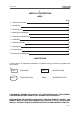
LIE&LQA0 1 INDEX & CONVENTIONS INDEX Page 1 Index & Conventions 1 2 Introduction 2 3 Receiving unit 5 4 Warnings for installation 7 5 Warnings for maintenance 9 6 Installation 12 7 Antenna assembly 13 8 Light signals 14 9 Programming 15 10 Receiving unit diagnostic 16 CONVENTIONS In this manual, all important information is indicated using the following symbols and conventions: ! abcd. . . : WARNINGS abcd. . . : INSTRUCTIONS abcd. . . : TECHNICAL DATA abcd. . .
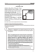
LIE&LQA0 2 INTRODUCTION Industrial radio remote controls are used to command machines from a distance. Each industrial radio remote control is made up of a portable transmitting unit, from which the user can remotely control the machine, and a receiving unit installed on board the machine itself. The transmitting unit uses radio frequencies to transmit a coded message which contains a value called address.
LIE&LQA0 ! Autec cannot be held responsible if the radio remote control is installed on applications that are different from those permitted: PERMITTED USES Material lifting machines (construction cranes, industrial bridge cranes, machines for moving material in general, . . . ). FORBIDDEN USES Machines installed in areas where equipment with explosion-proof characteristics are being used. Machines for moving, raising and transporting people.
LIE&LQA0 INSTRUCTIONS FOR DOCUMENT MANAGEMENT The following minimum documentation is supplied with each radio remote control: - transmitting unit manual - receiving unit manual - battery charger manual - a guarantee certificate - the radio remote control technical data sheet. Make sure that the following documents have been supplied: if they are not, request them from Autec. Please specify the radio remote control serial number.
LIE&LQA0 3 RECEIVING UNIT The receiving unit Type R102 may be used with the following transmitting units: - LIGHT SERIES - MODULAR SERIES.
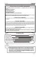
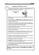
LIE&LQA0 RECEIVER EXTENSION Also available is a receiver extension, which adds another 6 commands to those on the base unit. D F4 D G G output terminal block flat cable for connection receiving unit extension In order to connect the receiving unit to its extension, insert the ribbon cable into the connector, which is positioned next to the antenna connector (F).
LIE&LQA0 ! 4 WARNINGS FOR INSTALLATION Installation should only be carried out by qualified people and in accordance with installation country rules. THE INSTALLER MUST MOUNT the receiving unit so that the output terminal blocks always faces upwards. DO NOT MODIFY or TAMPER WITH the radio remote control, the machine or its electric systems. DO NOT PERFORATE the receiving unit for any reason whatsoever.
LIE&LQA0 The presence of vibrations can compromise receiving unit performance: it is therefore advisable to use suitable rubber mountings. Antenna assembly is covered in the installation instructions (refer to chapter 7 for details and warnings). ! SUPPLY THE RECEIVING UNIT BY A SAFETY ISOLATING TRANSFORMER. The source of POWER SUPPLY must be protected from short circuit. WHEN WELDING ON THE MACHINE during installation or use, remove all electrical connections including the aerial from the receiver unit.
LIE&LQA0 5 WARNINGS FOR MAINTENANCE ! While carrying out maintenance operations, THE RELEVANT PERSONNEL MUST ENSURE T H A T T H E E L E C T R I C PA N E L I S DISCONNECTED FROM ALL SOURCES OF SUPPLY. Any faults should be repaired by authorised Autec personnel using original Autec spare parts only. Failure to comply with this requirement may invalidate the guarantee offered.
LIE&LQA0 ROUTINE MAINTENANCE The following instructions allow to maintain the radio remote control in a perfect condition, guaranteeing it to function safely and correctly for a long period. Special applications may need more specific routine maintenance interventions to be carried out at different periods. These instructions do not in any case substitute the norms and laws that regulate work safety, nor do they limit the responsibility of the purchaser and user of the radio remote control.
LIE&LQA0 SPECIAL MAINTENANCE ! Any fault should be repaired by authorised Autec personnel (contact Service), using original Autec spare parts only. AUTHORIZED SERVICE CENTER When it is necessary to carry out special maintenance (radio remote control repair and replacement of damaged or faulty parts), do not contact anyone other than our Authorized Service Center.
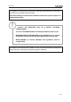
LIE&LQA0 6 INSTALLATION If installed inside an electric cabinet, the receiving unit must be installed exclusively on DIN EN 60 715 rail (ex DIN EN 50 022). Follow instructions below for easy and fast assembly and disassembly. ASSEMBLY Clip the upper part of the receiving unit over the DIN rail. Using a screwdriver, push the hook on the base of the receiving unit downwards until the receiving unit pushes easily onto the DIN rail.
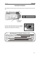
LIE&LQA0 7 ANTENNA ASSEMBLY ! The antenna must only be assembled by qualified technicians. The antenna stylus should never come into contact with metallic parts. An antenna must be installed outside the electric cabinet to ensure a reliable radio link from the transmitting unit to the receiving unit. 1 Insert the antenna cable into the connector on the receiving unit (see photo 1) and fit the antenna on a metallic surface (e.g. electric panel, bracket . . .) (see photo 2).
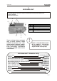
LIE&LQA0 8 LIGHT SIGNALS RL 14 RL 13 RL 12 RL 11 RL 10 RL 9 RL 8 RL 7 RL 6 RL 5 RL 4 RL 3 RL 2 RL 1 START/ SAFETY STOP/ENA POWER Each receiving unit has lights that indicate the state of the receiving unit and its relays. POWER: indicates that the receiving unit is powered STOP/ENABLE: indicates that the radio link from the transmitter is active.
LIE&LQA0 9 PROGRAMMING ! The dip switches must be programmed when the receiving unit is not powered and can be done only by authorised personnel. DIP SWITCHES ON E16SRXUS1 RADIO RECEIVING MODULE The group of eight dip switches found in the module permits the programming of different operating mode and the setting of operating frequency. The programming set in the other group of four dip switches must never be modified.
LIE&LQA0 10 RECEIVING UNIT DIAGNOSTICS If the "machine+radio remote control" system does not start, firstly determine whether the problem is caused by the radio remote control or the machine. Before carrying out any detailed tests, check if the machine functions with the cabled control panel: if it does not operate normally, the problem lies with the machine itself. If, however, the machine operates normally using the cabled control panel, the problem lies with the radio remote control.
Appendix: FREQUENCY TABLE E16SRXUS1 MHz DIP SWITCH DIP SWITCH MHz 3 4 5 6 7 8 3 4 5 6 7 8 902.150 903.050 915.350 916.250 ON OFF OFF OFF OFF ON OFF OFF OFF ON OFF ON 903.850 OFF OFF OFF OFF ON ON 917.050 ON OFF OFF OFF ON ON 904.650 OFF OFF OFF ON ON ON 917.850 ON OFF OFF ON ON ON 905.525 OFF ON OFF OFF OFF ON ON ON OFF OFF OFF ON 906.325 OFF ON OFF ON OFF ON 918.675 919.525 ON ON OFF ON OFF ON 907.175 OFF ON OFF OFF ON ON ON OFF OFF ON ON 907.975 OFF ON OFF ON 920.
Via Pomaroli, 65 36030 Caldogno (VI) ITALY Tel : ++39 - 0444/901000 r.a. Fax: ++39 - 0444/901011 email: info@autec.it http://www.autec.