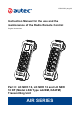
LIULK1N03_eng-00 Instruction Manual for the use and the maintenance of the Radio Remote Control Original instructions Part C: LK NEO 10, LK NEO 12 and LK NEO 10 DF (Model LKN Type LA2EM, DA2FM) Transmitting Unit AIR SERIES
WARNING THIS PART OF THE MANUAL CONSISTS OF: Part C - Information, instructions and warnings for the LK NEO 10, LK NEO 12 and LK NEO 10 DF (Model LKN Type LA2EM, DA2FM) Transmitting Unit. The Manual consists of Part A – General, Part B – Conformity and Frequencies, Part C – Transmitting Unit, Part D – Receiving Unit, Part E – Battery and Battery Charger, plus the Technical Data Sheet.
It is also the responsibility of the Manufacturer and of the design professionals of the Machine on which the Autec Radio Remote Control is to be installed and used to be certain that the structure, condition, organization and markings of the Machine as installed at the facility is appropriate for and will allow for the safe and reliable use and control of the Machine through the Autec Radio Remote Control interface.
IT IS THE RESPONSIBILITY OF THE OWNER AND FACILITY OPERATOR, AND THEIR OFFICERS, MANAGERS AND SUPERVISORS, to be certain that all Users of the Autec Radio Remote Control and that all Persons who are or will be working with or near the Machine operated by or through the Autec Radio Remote Control are fully and properly educated and trained by qualified Personnel in the proper and safe use of the Autec Radio Remote Control and of the Machine, including without limitation complete familiarity with and understa
INDEX 1 2 3 4 5 6 7 8 Information on the use of instructions ................................................................. 8 1.1 Structure of the Instruction Manual ................................................................. 8 1.2 Caption and terminology ............................................................................... 10 1.3 Symbols ....................................................................................................... 10 1.
9 10 11 12 8.10 Vibration alarm ............................................................................................. 8.11 Starting up the Radio Remote Control .......................................................... 8.12 Command activation ..................................................................................... 8.13 Radio link interruption ................................................................................... 8.14 Transmitting Unit automatic switch off ................
Information on the use of instructions 1 Information on the use of instructions Before reading this part of the Manual, you must read and understand the general part (Part A) of the Manual provided with the Radio Remote Control. 1.
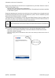
Information on the use of instructions 9 Usage and maintenance instructions are supplemented by the Radio Remote Control's Technical Data Sheet, that: -- describes the Transmitting Unit's configuration, -- indicates the relation between commands sent by the Transmitting Unit and those available on the Receiving Unit.
1.2 Information on the use of instructions Caption and terminology Contact Autec if any of the instructions, symbols, warnings or images are not clear and understandable, or if you have doubts or questions.
Information on the use of instructions 1.4 11 To whom the instructions are addressed Addressees of instructions are listed in the paragraph with the same title in the general part: please refer to that part. 1.5 Instruction storage Regulation for the storage of instructions are described in the paragraph with the same title in the general part: please refer to that part. 1.
Brief product presentation 2 Brief product presentation 2.1 Series, Radio Remote Control and Unit The object of this part of the Manual is the LK NEO 10, LK NEO 12 and LK NEO 10 DF (Model LKN Type LA2EM, DA2FM) Transmitting Unit of an Autec Air series' Radio Remote Control. Autec Air series' Radio Remote Controls are designed to be used on Machines and provide a command interface to their command and control system, to be used from an appropriate distance and position. 2.
Description of the Transmitting Unit 13 3 Description of the Transmitting Unit 3.
Description of the Transmitting Unit 3.
Technical data 15 4 Technical data 4.1 Technical data of LK NEO 10 and LK NEO 12 Transmitting Units (Model LKN Type LA2EM) Power supply (battery MHM03) ............................................................................... 3.6V Power supply (battery LPM01) ................................................................................ 3.7V Antenna ................................................................................................................... internal Housing material ....
Plates 6 Plates The following instructions refer to the plates on different types of Radio Remote Controls where the LK NEO 10, LK NEO 12 and LK NEO 10 DF (Model LKN Type LA2EM, DA2FM) Transmitting Unit may be used. 6.1 Plates on the LK NEO 10, LK NEO 12 and LK NEO 10 DF (Model LKN Type LA2EM, DA2FM) Transmitting Unit in a Radio Remote Control Plate Position Content Key ID 0-1 (if present) Radio Remote Control identification plate 6.
Plates 6.
Light signals 7 Light signals 7.1 Light signals on LK NEO 10 and LK NEO 12 Transmitting Units (Model LKN Type LA2EM) A Red LED B Green LED C LEDs for "Data Feedback" function The LK NEO 10 and LK NEO 12 Transmitting Units always have a green LED [B] and a red LED [A] that provide information regarding the Radio Remote Control. Symbol Meaning This symbol identifies the red LED [A]. This symbol identifies the green LED [B].
Light signals 19 Signal The green LED [B] is off. The green LED [B] is lit with a steady light. The green LED [B] repeats the sequence: two blinks and a pause. Meaning The Transmitting Unit is off. The Transmitting and Receiving Unit do not communicate. The working range of the remote control has been exceeded for more than 20 seconds. The green LED [B] repeats the sequence: three blinks and a pause. The Receiving Unit does not communicate with the transmitting Unit.
Light signals Signal Meaning The green [B] and red [A] LEDs are steady on during start up. A wrong "Key ID 0-1" or "ID internal tx memory" has been inserted in the Transmitting Unit, or this is a "BACK-UP UNIT". The green [B] and red [A] LEDs blink 3 times per second during start up. The green LED [B] is lit with a steady light and the red LED [A] blinks two times per second during start up. The "Key ID 0-1" or the "ID internal tx memory" is damaged. The START pushbutton is activated.
Light signals 7.2 21 Light signals on the LK NEO 10 DF Transmitting Unit (Model LKN Type DA2FM) Display icons A Red LED B Green LED D Battery E Radio link The following icons are always available on the display of LK NEO 10 DF Transmitting Units: -- red LED [A] and green LED [B] providing information about the Radio Remote Control, -- battery [D] providing indication of the battery power level, -- radio link [E] providing indication of radio link strength.
Light signals Signal The green LED [B] repeats the sequence: two blinks and a pause. Meaning The working range of the remote control has been exceeded for more than 20 seconds. The green LED [B] repeats the sequence: three blinks and a pause. The Receiving Unit does not communicate with the transmitting Unit. If the Transmitting Unit communicates with the Receiving Unit, it is possible to send commands. The green LED [B] blinks fast. The Transmitting and Receiving Unit communicate.
Light signals 23 Signal Meaning The green LED [B] is lit with a steady light and the red LED [A] blinks two times per second during start up. The START pushbutton is activated. The green [B] and red [A] LEDs blink alternating. 30 s left before the Transmitting Unit automatically switches off. The green LED [B] repeats the sequence: 3 blinks and a pause, and the red LED [A] is steady on during start up. The UNPAIR procedure has been carried out. 7.2.
General operating instructions 8 General operating instructions 8.1 Power keyswitch When the Transmitting Unit has a power keyswitch, this can be: -- A mechanical key (see paragraph 8.1.1) -- A Key ID 0-1 (see paragraph 8.1.2). The Radio Remote Control cannot work if the power keyswitch is not inserted in the Transmitting Unit. 8.1.1 Mechanical key The mechanical key makes it possible to power the Transmitting Unit. 8.1.
General operating instructions 8.2 25 START pushbutton The START pushbutton is used to: -- start the Radio Remote Control (see paragraph 8.11), -- activate the horn when the Radio Remote Control is started. 8.3 STOP pushbutton When the STOP pushbutton is activated, the Machine stops and the Transmitting Unit switches off.
8.6 General operating instructions Enabling switch A three-position actuator, called "Enabling switch", can be present on the left side of the Transmitting Unit. The "Enabling switch" is an actuator that needs to be activated at the same time as other actuators in order to consent to send the corresponding commands to the Machine. The Manufacturer and/ or the Installer decide which actuators need to have the "Enabling switch" activated to send commands to the Machine.
General operating instructions 8.7 27 Battery The Air series' Transmitting Units can only be powered by Autec rechargeable batteries. For any warnings and instructions regarding the battery, see "Part E" in the Instruction Manual. 8.7.1 Battery insertion Push the battery towards the contacts on the Transmitting Unit (1) and insert it inside the housing (2).
General operating instructions 8.7.4 Indication of the battery charge level in the LK NEO 10 and LK NEO 12 Transmitting Unit (Model LKN Type LA2EM) Perform the following procedure to check the charge level of the battery in the LK NEO 10 and LK NEO 12 Transmitting Units: 1. switch off the Transmitting Unit and unlock the STOP pushbutton, 2.
General operating instructions 8.9 29 Zero-G sensor The Transmitting Unit is equipped with a Zero-G sensor only upon request of the Machine Manufacturer and/or of the Installer, who are responsible for the decision on the conditions for the Zero-G sensor to activate. The Zero-G sensor can activate for one or more of the following causes: -- Impact: the Zero-G sensor activates when the Transmitting Unit impacts with at least a 30-centimetre movement and with an acceleration higher than 2g.
8.11 General operating instructions Starting up the Radio Remote Control Starting up the Radio Remote Control consists in establishing a radio link between the Transmitting Unit and the Receiving Unit. The Radio Remote Control start up is protected by means of a power keyswitch and/or a PIN code to prevent unauthorised use of the Machine. To start up the Radio Remote Control, you need to insert the power keyswitch and\or to key in the PIN code according to the procedure provided in paragraph 8.11.
General operating instructions 31 8.11.2 PIN code start up (no power keyswitch) When the Receiving Unit is correctly powered on, perform the following procedure; press each pushbutton within 3 seconds after releasing the previous one: 1. Insert a charged battery in the Transmitting Unit (see paragraph 8.7.1), 2. press the START pushbutton and hold it down until the green LED illuminates, 3.
General operating instructions 8.11.4 Procedure to modify the PIN code If a PIN code is needed for the Transmitting Unit, it can be modified to limit the use of the Radio Remote Control. To modify the PIN code, perform the following procedure with the Transmitting Unit switched off and the STOP pushbutton released. 1. Press pushbuttons FUNCTION and START and hold them down until the green LED blinks (1 blink per second). 2.
General operating instructions 33 8.14.1 Low battery The Transmitting Unit indicates if the battery is not sufficiently charged. -- the red LED blinks slowly (one blink per second): the battery has less than 1h run time. -- The red LED blinks fast: the battery has a 10 minute run time from the first signal, after which the Transmitting Unit automatically switches off. It is necessary to bring the Machine to a safe state and replace the battery with a charged one (see paragraph 8.7). 8.14.
8.16 General operating instructions "Data Feedback" function The "Data Feedback" function acts through the LED array or the display. The User receives information and/or signals concerning some particular situations and the movements of the controlled Machine by means of this function. During normal Radio Remote Control operation, pay particular attention to the indications displayed and signalled by the display or through the LEDs: they can be helpful to evaluate the Machine working status.
General operating instructions 8.17 35 BACK-UP UNIT If the Transmitting Unit cannot be used, it can be replaced with a Transmitting Unit called "BACK-UP UNIT"; you need to ask for it from Autec. It is identical to the Unit that can no longer be used; the only difference is the presence of the plate “BACK-UP UNIT” on the battery housing. Set DIP switch 2 in the "BACK-UP UNIT" as shown in the Technical Data Sheet.
9 Instructions for the User Instructions for the User The chapter "Instructions for the User" in "Part A" of the Instruction Manual contains the warnings for the use that add to those provided in this chapter. Therefore, please refer to that part of the Manual.
Instructions for the User 37 -- not perform any operation if the tests mentioned in the previous two points did not give positive results; -- make sure that the Radio Remote Control operation and the consequent Machine movement occur in safety conditions, to prevent hazards to people and/or property; -- adopt the necessary caution to avoid that the Machine operation causes dangerous situations of any type; to this end, the User's physical and health status shall be taken into account too; -- avoid leaving
9.3 Instructions for the User Belt and pouch with belt The LK NEO 10, LK NEO 12 and LK NEO 10 DF (Model LKN Type LA2EM, DA2FM) Transmitting Unit always comes with a belt or a pouch with belt: the User must mount and use the belt and the pouch with belt as explained in the paragraphs 9.3.1 and 9.3.2. 9.3.
Instructions for the User 7 AUTEC - AIR SERIES 39 8 LIULK1N03_eng-00
Instructions for the User Use The User must wear the Radio Remote Control with the belt as shown in the photo below, to avoid its fall, loss, loss of control, accidental contact and improper use. If the Transmitting Unit and the belt are used in a different way from the one described in the above mentioned figure, this constitutes improper use and may lead to damage to the Transmitting Unit, to the User, to people and/or property. Replace the belt or harness if it is damaged or worn.
Instructions for the User 41 9.3.
Instructions for the User Use The User must wear the Radio Remote Control with the pouch with belt as shown in the photo below, to avoid its fall, loss, loss of control, accidental contact and improper use. If the Transmitting Unit and the pouch with belt are used in a different way from the one described in the above mentioned figure, this constitutes improper use and may lead to damage to the Transmitting Unit, to the User, to people and/or property.
Maintenance 10 43 Maintenance Instructions for correct Radio Remote Control maintenance are described in the chapter "Maintenance" included in "Part A" of the Instruction Manual. Therefore, please refer to that part of the Manual. 11 Malfunction signalled by the Transmitting Unit The table below lists malfunctions that are signalled by LEDs on the Transmitting Unit and the solution to those malfunctions.
Maintenance Signals Possible reason Solutions The red LED blinks twice per second during start up. At least one of the commands that were checked at start-up is enabled or damaged (see Technical Data Sheet). Move the actuators related to the commands monitored during the start up to the rest position. The red LED blinks three times per second during start up. The battery is flat. Replace the battery with a charged one. The red LED is steady on for two seconds during start up.
Decommissioning and disposal 12 45 Decommissioning and disposal Instructions for correct decommissioning and disposal of Radio Remote Controls are described in chapter "Decommissioning and disposal" in "Part A" of the Instruction Manual. Therefore, please refer to that part of the Manual.
Via Pomaroli, 65 - 36030 Caldogno (VI), ITALY PH: +39 0444 901000 - Fax: +39 0444 901011 info@autecsafety.com - www.autecsafety.