
Instruction Manual

LIUDPP002_eng-00 AUTEC
36
6.2 Sta training: inallation and maintenance
All inallation and maintenance operations relating to the Autec Radio Remote Control syem
mu be carried out ONLY by qualified technicians. Without limitation on the foregoing, such
technicians mu be trained and qualified with respect to:
- The activity to perform
- Warnings resulting from the risk assessment, concerning the Radio Remote Control
inallation and/or maintenance
- All applicable Laws, Regulations and Standards, even local, including also safety rules
- Operations and requirements of the Machine on which the Radio Remote Control is to be
inalled
- Inructions and warnings provided in the Manual and any other documents related to the
Radio Remote Control and to the radio remote controlled Machine
- Directions by the Machine Manufacturer and by the Person in charge for safety in the workplace
where the syem "Machine + Radio Remote Control" is used.
General instructions for installation and maintenance are provided in chapter 6 and in chapter
9 respectively.
Instructions for the dierent Units are described in the specic Manual's parts related to the
Units.
Therefore, please refer to that parts of the Instruction Manual.
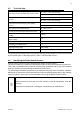
6.3 Classication of commands
This paragraph describes the classification of commands in the Radio Remote Control: such
information is useful during inallation and maintenance.
6.3.1 Command type: analogue, digital or direction command
Commands sent by the Transmitting Unit can either be analogue, digital or direction commands.
Analogue commands generate proportional outputs as a function of the position of the
corresponding actuator.
Digital commands switch the atus of their corresponding output, according to the position of
the related actuator. This atus can either be on or off.
Direction commands are digital commands paired with analogue commands, and are used to
enable the movement in a specific direction.
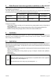
6.3.2 Name of commands
All commands activated by the Transmitting Unit are identified with abbreviations such D1, D2,
H1, L1, etc.
Those abbreviations are provided in the Technical Data Sheet that mu be used when inalling
the syem, and in particular:
- In the drawing of the Transmitting Unit, where commands and their layout are indicated
- In the wiring diagram of the Receiving Unit.
This is helpful to highlight the relation between the commands sent by the Transmitting Unit
and those available on the Receiving Unit.