
Instruction Manual

LIUPJQ001_eng-00AUTEC
15
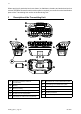
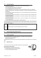
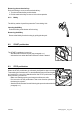
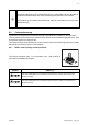
The Transmitting Unit always has a green LED [B] and a red LED [A] that provide information
regarding the Radio Remote Control.
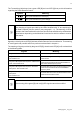
Symbol Meaning
This symbol identifies the red LED [A]
This symbol identifies the green LED [B]
The meaning of signals provided by the LEDs identified with “C” are explained in
the Data Feedback function section (see paragraph 8.15). The meaning of LEDs
related to the Data Feedback function are decided and eablished by the Machine
Manufacturer depending on the Machine's functions for which he wants to receive
information.
Signals provided by the red LED [A] indicate a Radio Remote Control malfunction. The meaning
of such signals and possible actions to perform are described in chapter 11.
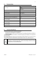
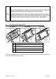
The meaning of signals provided by the green LED [B], when the red LED [A] is off, are described
in the following table.
Signals Meaning
The green LED is off. The red LED is off. The Transmitting Unit is off.
The green LED blinks fa.
The red LED is off.
The Transmitting and Receiving Unit
communicate.
The green LED repeats the sequence: a blink and a
pause. The red LED is off.
The Radio Remote Control is arted and the Units
communicate via radio link in the 863-870MHz or
2400-2483.5MHz frequency band.
The green LED repeats the sequence: two blinks
and a pause. The red LED is off.
The Radio Remote Control is arted and the Units
communicate via radio link in the 915-928MHz
frequency band.
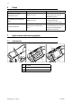
The green LED repeats the sequence: three blinks
and a pause.
The red LED is off.
The Radio Remote Control is arted and the Units
communicate via cable control.
The meaning of the green [B] and red [A] LED signals cannot be modified.